Despite the mixed reviews
(1), back in 2006 I decided to purchase a Comet
CHA-250BXII antenna. These are sold as a “broadband HF vertical that does not require
radials”. Some people think they’re the greatest thing since sliced bread; others
rate them as a glorified dummy load. Interestingly, there don’t seem to be too many
people with an intermediate view; they either love it or hate it.
Physically, the
antenna consists of a 7m aluminium element fitted to the top of a 140mm tall “black
canister”, the contents of which seem to be the subject of much speculation.
Electrically,
the vertical element has the following lengths:
3.60 MHz 0.084λ
7.10 MHz 0.166λ
10.13 MHz 0.236λ (~1/4λ)
14.20 MHz 0.331λ (~1/3λ)
18.17 MHz 0.424λ
21.20 MHz 0.495λ (~1/2λ)
24.95 MHz 0.582λ
28.50 MHz 0.665λ (~2/3λ)
When the antenna had been in use for a few months it developed
a fault which, while it prevented me from transmitting into the antenna (SWR went
high), had no noticeable affect on its receiving performance. At this point I had
two choices:
(a) Return it to the place of purchase since it’s still under warranty
or
(b) Attempt to find and fix the fault.
Being the inquisitive sort that I am,
I decided to try and fix it. This entailed some risk since it would obviously void
the warranty and there was no guarantee of success. The following is a description
of the disassembly procedure I used and what I found inside.
A word of warning!This device is not designed to be dismantled. While everything is screwed together,
every thread has been liberally coated with glue during manufacture and only comes
apart with great difficulty. I had to saw through the plastic top cap to remove
it. If you decide to dismantle yours at any time then do so at your own risk.
The
following pictures are actually in reverse order because they were taken after I
had dismantled the unit. This first image is of the antenna base assembly. This
was taken after I had put everything back together. You can see the silicone I applied
to the joints to help seal out moisture (which turned out to be the cause of the
fault).
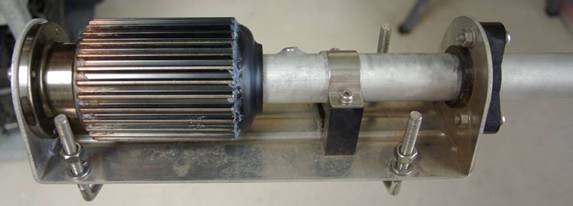 Image 1 - Antenna Base Assembly
Image 2 shows the matching unit (a.k.a. black canister, dummy load) removed from the antenna base.
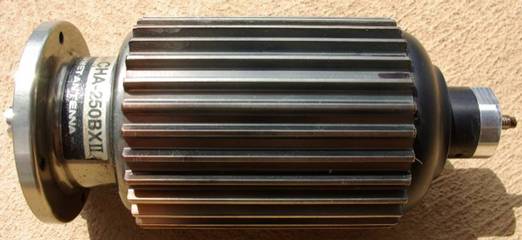 Image 2 - The mysterious "Black Canister"
Image 3 shows how the top and bottom sections are screwed into the central section (bit with the
fins). Before the top can be removed, you must first remove a small grub screw that locks the
top aluminium piece in place. You can then start to unscrew the central spigot at the top. Note
that this has a wire soldered into the centre of it. Don’t even bother trying to undo this joint
with your average soldering iron; it requires too much heat. As you undo this spigot you will be
twisting the attached wire. This doesn’t matter since there’s plenty of it inside. Once the
screw has been undone to the end of the thread, hold the end spigot with a pair of pliers and heat
with a gas blowtorch to melt the solder and pull the spigot off the wire.
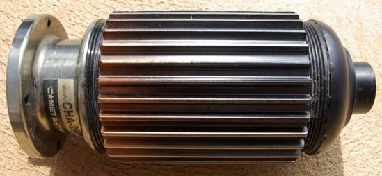 Image 3 - Showing how the top and bottom sections are screwed in.
Image 4 shows the parts in the top section assemble. Once the spigot, washers, etc. have been
removed the black plastic cap can, in theory, be unscrewed. In practice, the torque required to
break the glue on the threads is colossal. What I did next (after trying various things involving
hammers and screwdrivers) was to carefully saw into the plastic cap (with a hacksaw) right next to
the fins. Bear in mind that, at this stage, I didn’t know the cap was screwed in; I assumed it was
just glued in. I had to cut to a depth of 10-12mm before the cap came off. This left the part
with the threads still in the top of the central section. Using a hacksaw blade I made two cuts
through this piece 180° apart. After this a light tap with a hammer was enough to break the glue
and the two pieces came out. With hindsight you could perhaps drill some holes in the cap so that
a specially fabricated lever can be attached to it with screws. You might then be able to apply
sufficient torque to unscrew it in one piece, but I still think it unlikely. At this point I was
left with the plastic cap in three pieces; the top cap plus the threaded section in two halves.
These were put back together with superglue and some small self-tapping screws (the cap in images
3 and 4 is after I put it back together).
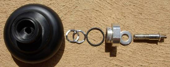 Image 4 - Top section parts.
Images 5 and 6 show the matching unit with the top cap removed. There are two wires going to the
SO-239 socket in the base. These are just visible through the central assembly. In my case, the
ground wire to the socket was already broken due to corrosion. After much poking and prodding with
a screwdriver I managed to break off the second wire at the centre pin of the coax socket. The
central assembly was then pulled out of the canister.
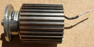
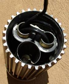 Image 5
Image 6
Image 5
Image 6
Next I used two of the mounting holes in the base to attach the canister to a piece
of 4mm thick steel strip which was in turn held in a vice. A vehicle oil-filter
removal tool was then used to unscrew the central section from the base. Even with
this arrangement, I still had to heat the join between the two sections with a gas
blowtorch to soften the glue before I could undo it (hence the need to break wires
and remove the insides first). This is the cause of the discolouration visible on
the lower part of the fins in images 2 and 3. Image 7 shows the aluminium sleeve
after removal from the base.
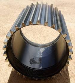 Image 7 - Threaded aluminium sleeve.
THE BITS INSIDE
Images 8 to 12 show the matching unit assembly. The small fibreglass cylinder in
image 8 is used as packing to make sure the parts can’t move around. The matching
unit appears to be a transformer with a ratio of about 12:1. The ring at the end
of the wire with clear insulation goes under the nut on the SO-239 socket while
the green/yellow wire goes to the centre pin. The black wire on the right goes to
the antenna element.
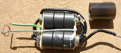 Image 8 - Matching unit side ‘A’.
 Image 9 - Matching unit side ‘B’.
The brass tubes through the toroids are the first “turn”. The two tubes are joined
at the top and this point is connected to ground. The bottom end of one tube is
connected to the coax centre while the bottom of the other end connects to the start
of the coil that goes through the tubes. The end of the last turn goes through one
of the tubes then loops back to the top (left hand tube in image 10).
 Image 10
Image 11
Image 12
Image 10
Image 11
Image 12
Images 13, 14 and 15 show the parts in the bottom section assembly. Note that the
base section is threaded to take the SO-239 socket. Image 16 shows the matching
unit refitted to the base section prior to reassembly.
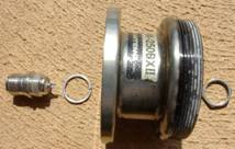
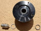
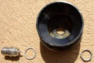 Image 13
Image 14
Image 15
Image 13
Image 14
Image 15
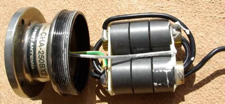 Image 16 - Matching unit fitted to base section.
|
|
|
|
|
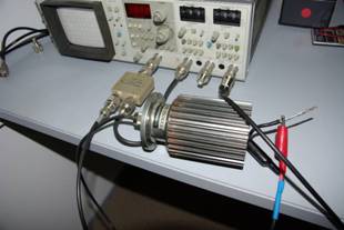
| Image 17 – Test setup. |
|
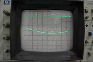
Image 18 – Test results. |
|
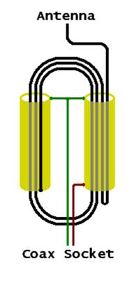
Image 19 - Internal circuit. |
Image 18 shows the loss over the range 3 – 30 MHz. The upper trace is the 0 db line.
The markers are at 10 MHz intervals. The vertical scale is 2.5 db per division.
This is not an entirely accurate test because the output impedance of the matching
unit is nowhere near 50Ω.
The sketch above gives a clearer view of how the matching unit is wired up. I will
try to answer any questions you may have regarding the construction of this device.
Please send them to cha250 at vk5zd.com (replace 'at' with @).
73
Iain Crawford
VK5ZD
References:
(1) eHam.net - http://www.eham.net/reviews/detail/5175
HOME