29-Jan-2008 - From Martin Ehrenfried, G8JNJ
I have now made a copy using 25mm ferrite rings and 15mm copper water pipe as the inner cores.
The through loss curves when terminated in 50 ohms seem to be very similar to your genuine unit. See attached photos.
As another test I terminated the input with a 50 ohm load and then measured the impedance of the secondary winding with an Autek VA1.
| Input 50 Ohms | ||||
| MHz | R (ohms) | J (ohms) |
So the secret seems to be that it's a very lossy 4:1 balun !
I'm a bit mystified by the odd construction though. I wonder if it was wound correctly in the factory. The way the first turn of the secondary loops outside the ferrite core and then doubles back on itself, before connecting to the output is very odd. It's almost like someone made a mistake and then lost the rest of the surplus cable by folding it up and stuffing it back inside the assembly. Pictures sent by Martin can be viewed from these links: Picture 1 Picture 2 Picture 3 |
|
| 0.5 | 8 | -41 | ||
| 1 | 22 | 73 | ||
| 1.5 | 43 | 99 | ||
| 1.9 | 68 | 112 | ||
| 3.6 | 143 | 128 | ||
| 7.1 | 245 | 130 | ||
| 10.1 | 297 | 99 | ||
| 14.1 | 279 | 52 | ||
| 18.1 | 292 | -24 | ||
| 21.1 | 252 | -46 | ||
| 24.9 | 208 | -59 | ||
| 29 | 193 | 5 | ||
29-Jan-2008 - From Hidehiko Koguchi, JI1AVY
I am JI1AVY, Hidehiko (HIDE) Koguchi from Tokyo, Japan. I was impressed very much
with your disassemble report of CHA250. You did a great work. For your reference,
let me tell you some additional information.
JJ1GRK, Takagi OM contributed on CHA250 type broad band antenna to Japanese CQ magazine
annex #1, published in August 2007. He defined CHA250 type as MLB(Magnetic Longwire
Balun) antenna. According to his article, MLB is originally developed as a impedance
matching transformaer at the passive antenna termial of HF radio. Also the transformer
has another feature that you do not need an earth side element when you deploy the
MLB. (Sorry I can not discribe details of this feature because my technical knowledge
is limited.) Then he experimented on the MLB deployed broadband antenna again and
again. He finally made his original MLB antenna.Through his experiments he tried
to assume a structure of CHA250B based on Xray photograph of its core unit.
So I think even he has never seen the disassembled inside of CHA250. Your work must
be the first ever in the world, at least, which have been published.
I have just sent your PDF URL to JJ1GRK (Hope Takagi OM would read it because he
does not like to receive an e-mail). And attached is a part of JJ1GRK article. Although
it is written in Japanese, you can find the figure of MLB and its SWR charts.
Attachment.
31-Jan-2008 - From Martin Ehrenfried, G8JNJ
I built a version of the CQ Ham Radio balun design using some small, long, ferrite
tube cores, and measured the secondary impedance as before.
It's basically a 4:1 balun. The first set of results is for the balun as shown in
the diagram, the second is the same balun with the feedback loop removed and the
wire just pulled out of the end where the loop is shown in the drawing.
The loop doesn't seem to do much except reduce the performance at the LF end, mainly
due to the loss of one half turn. I thought it may have been some sort of 'neutralising'
mechanism to improve the performance at the HF end, but this doesn't seem to be
the case. Have you any ideas regarding its purpose, other than present the cable
at the desired end of the assembly ?
| Jap balun with feedback loop | Jap balun no feedback loop | ||||||
| MHz | R (ohms) | J (ohms) | Z (ohms) | R (ohms) | J (ohms) | Z (ohms) | |
| 0.5 | 20 | -50 | 54 | 33 | -79 | 86 | |
| 1 | 52 | 69 | 86 | 89 | 92 | 128 | |
| 1.5 | 78 | 67 | 103 | 131 | 86 | 157 | |
| 1.9 | 90 | 66 | 112 | 149 | 71 | 165 | |
| 3.6 | 114 | 65 | 131 | 166 | 55 | 175 | |
| 7.1 | 138 | 87 | 163 | 179 | 48 | 185 | |
| 10.1 | 150 | 86 | 173 | 180 | 51 | 187 | |
| 14.1 | 177 | 91 | 199 | 188 | 64 | 199 | |
| 18.1 | 184 | 95 | 207 | 196 | 70 | 208 | |
| 21.1 | 192 | 103 | 218 | 186 | 86 | 205 | |
| 24.9 | 157 | 116 | 195 | 162 | 100 | 190 | |
| 29 | 161 | 115 | 198 | 155 | 105 | 187 | |
31-Jan-2008 - From Martin Ehrenfried, G8JNJ
I tried modifying the Comet balun copy to remove the 'feedback' loop. These are the results. A graph is also attached.
| Comet copy | Comet copy no feedback loop | ||||||
| MHz | R (ohms) | J (ohms) | Z (ohms) | R (ohms) | J (ohms) | Z (ohms) | |
| 0.5 | 8 | -41 | 42 | 12 | -82 | 83 | |
| 1 | 22 | 73 | 76 | 43 | 132 | 139 | |
| 1.5 | 43 | 99 | 108 | 87 | 177 | 197 | |
| 1.9 | 68 | 112 | 131 | 134 | 199 | 240 | |
| 3.6 | 143 | 128 | 192 | 294 | 202 | 357 | |
| 7.1 | 245 | 130 | 277 | 435 | 164 | 465 | |
| 10.1 | 297 | 99 | 313 | 459 | 140 | 480 | |
| 14.1 | 279 | 52 | 284 | 446 | 62 | 450 | |
| 18.1 | 292 | -24 | 293 | 438 | 18 | 438 | |
| 21.1 | 252 | -46 | 256 | 427 | -66 | 432 | |
| 24.9 | 208 | -59 | 216 | 335 | -20 | 336 | |
| 29 | 193 | 5 | 193 | 321 | -62 | 327 | |
I still don't understand how this works. The impedance match is miles off.
01-Feb-2008 - From Hidehiko Koguchi, JI1AVYHidehiko sent a translation for some of article in his previous message. I’ve reproduced it here. Please note: This information is from the Japanese CQ Magazine. The articles were written by JA6JCF (June 2005 issue) and JJ1GRK (August 2007 issue).
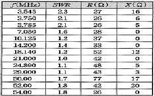 |
SWR measurements of a CHA250.
The SWR is less than 2.4:1 at all frequencies between 3.5Mhz and 54 Mhz. This measurement was done in these conditions 1. Feed point 5m high. 2. Using MFJ-259B 3. Connected by 1m of 5D-2V (50? Coax) between CHA250B and MFJ-259B. |
|
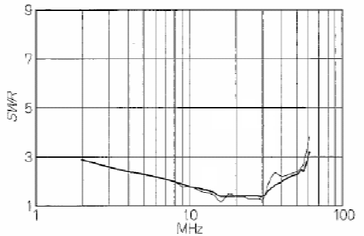 |
Case A – MLB (Magnetic Loop Balun) with 5.5m element.
To test the difference with and without the “return loop” in the winding. The MLB consists of 2 of SC-05-200. Each coil is 3 turns. Note: SC-05-200 is the part number of a ferrite core produced by NEC-TOKIN (http://www.nec_tokin.com/) The darker line is with the return loop, the lighter without it. Having the return loop improves the SWR. |
|
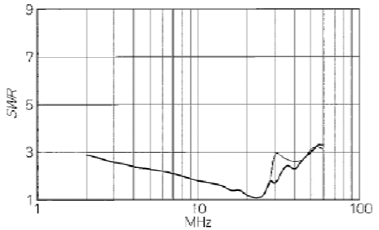 |
Case B – MLB (Magnetic Loop Balun) with 1.5m element.
Using the same MLB as in case A to test the affect of the antenna element length. The darker line is with the return loop, the lighter without it. The SWR is not as good with the shorther element although it’s still better with the return loop. |
|
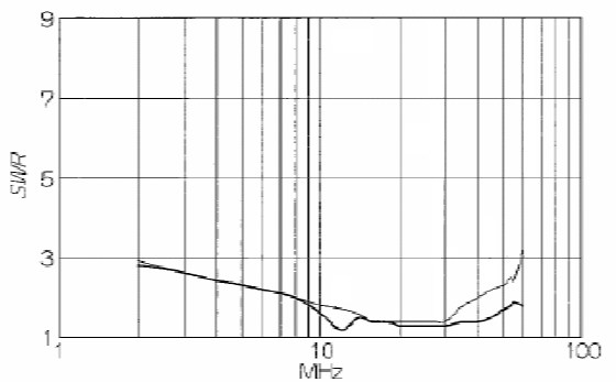 |
Case C – MLB with 5.5m and 6m element lengths.
Using the same MLB as in case A. The darker line is the 6m element, the lighter the 5.5m element. The 6m element gives a better SWR than 5.5m. The author also commented that element lengths over 6m show a worse SWR. Performance is sensitive to the element length. |
08-Feb-2008 - From Martin Ehrenfried, G8JNJ
I made some measurements on my copy. Some construction details can be found at:
http://g8jnj.webs.com/6_1%20Balun.pdf
The first table shows the input impedance with no antenna element connected. This
was measured directly on the input connector with no coax.
The second shows the impedance presented between the input connector earth and the
antenna connector. This was measured with the shortest leads possible, and no antenna
element connected.
Using similar information derived from measurements on an actual unit it should
be possible to characterise the type of ferrite being used.
12-Mar-2008 – From Marty KN0CK
Marty has also made a clone of this antenna. More details can be found at http://chat.qth.com/viewtopic.php?t=4455
Some pictures of Marty’s antenna can be seen here:
Close up of the matching unit
Matching unit on antenna with cover removed
Antenna Base
Antenna Base Close-up 1
Antenna Base Close-up 2
Antenna mounted outside
28-Mar-2008 - From Martin Ehrenfried, G8JNJ
Martin has done a lot more useful work on this type of antenna. Details can be found here:
http://www.g8jnj.net/cometcha250b.htm
http://g8jnj.net/broadbandhfvertical.htm
HOME