At various time I’ve seen people ask questions regarding grid antennas and
whether they should be covered with wire mesh to stop RF from ‘leaking’ through.
To try and resolve this question, I have conducted some simple tests.
At various time I’ve seen people ask questions regarding grid antennas and
whether they should be covered with wire mesh to stop RF from ‘leaking’ through.
To try and resolve this question, I have conducted some simple tests.
|
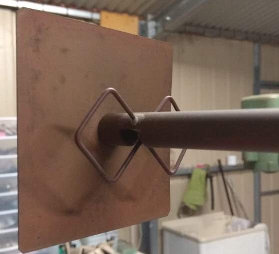 |
The first test was done in November, 2016 at 3.4GHz. The grid antenna was
originally made for 2.4GHz but I replaced the feed with a ‘bow tie’ and
sub-reflector made for 3.4GHz (pictured).
The testing process was fairly straight forward. I made a 3.4GHz half-wave
dipole antenna and connected it to my power meter (HP-435A). The grid antenna
was set up a few metres away and connected to one of my 3.4GHz transverters.
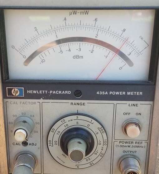
First I pointed the grid antenna directly at the dipole, transmitted a CW
carrier (25 watts) and noted the reading on the power meter (+4.3dbm).
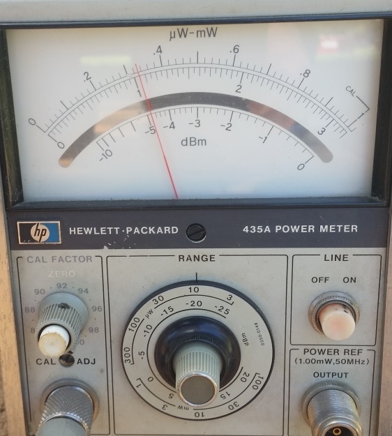
I then turned the grid antenna 180° and took another reading which was -24.8dbm,
a difference of just over 29db (i.e. a pretty good front to back ratio). From
this I conclude that there’s not much RF getting through the grid.
|
| |
 |
 |
 |
 |
 |
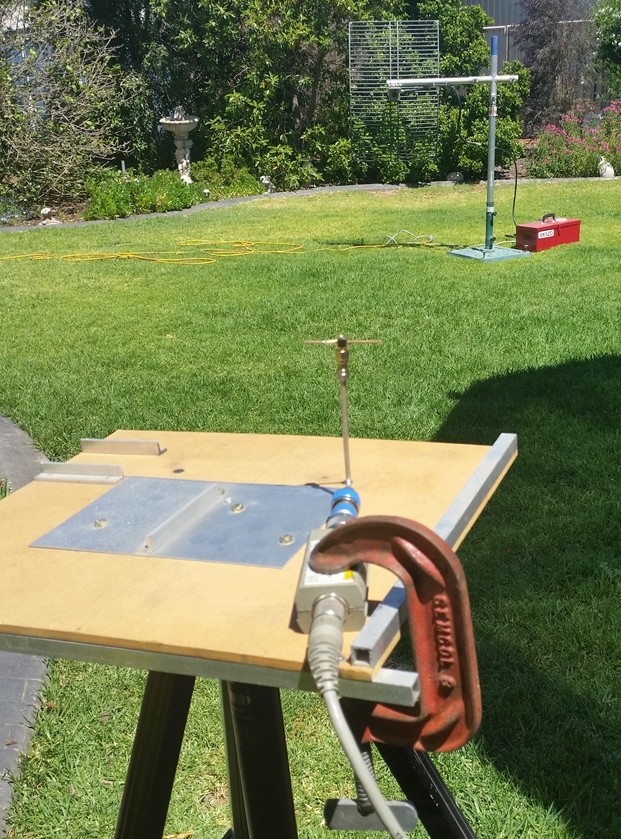
This is the dipole receive antenna connected
to the power meter head.
|
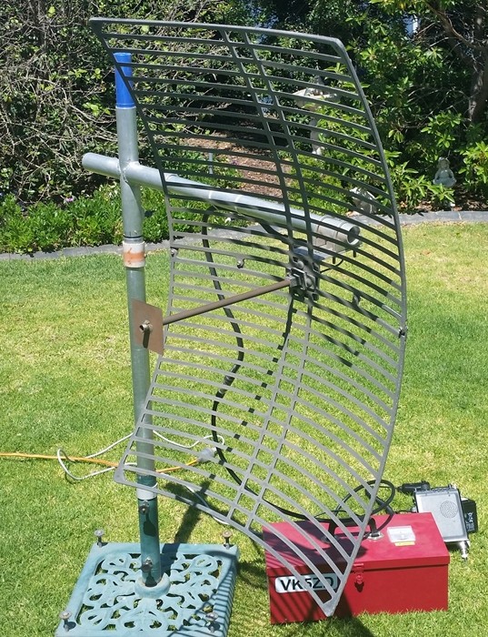
The grid antenna being
tested.
|
The power reading with the
antenna pointed at the
receive dipole.
|
The power reading after
turning the grid antenna
through 180°.
|
| |
The next two tests were done in August, 2018. Yes, a bit of a delay since the 3.4GHz test, but the question came up again in one of the forums.
These tests were carried out using a simple diode detector connected to a meter, so there no absolute measurement available. However, the results
do show that the grid antenna could be improved by adding a fine wire mesh to the surface, especially at 10GHz. The only drawback to this is that
the mesh would need to accurately follow the contours of the grid. While a suitable mesh will always reduce the RF leaking through, any surface
inaccuracies will reduce the amount of RF going in the direction you want it to.
The first set of images below show the result at 5.7GHz.
|
|
 |
 |
 |
There is some RF getting through but it's not a great amount. The meter shows 20% of the original voltage so this should
mean that 4% of the power is leaking through (power being proportional to the voltage squared), or just under 0.2db.
Therefore, it's probably not worth the effort of adding mesh for this band.
|
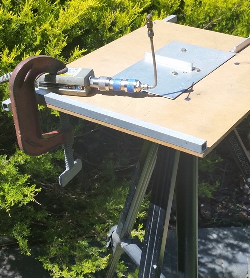
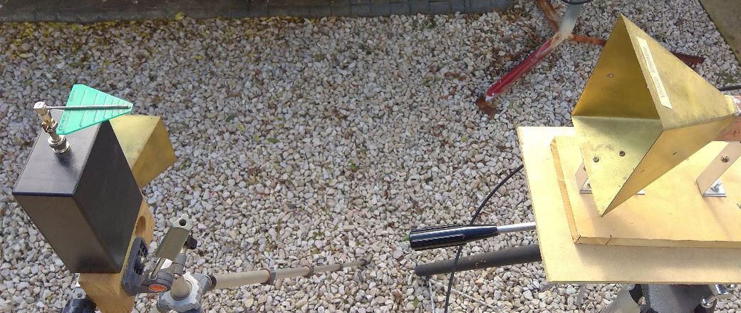
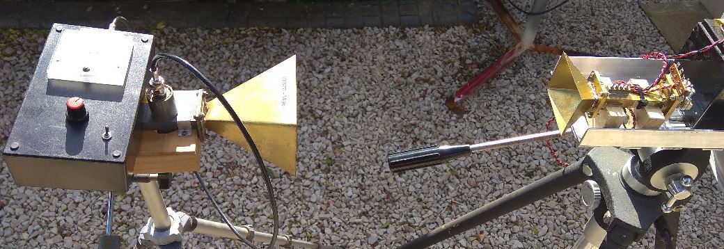
|
This is the 5.7GHz test setup. The RF source is on the right and the detector is on the left.
|
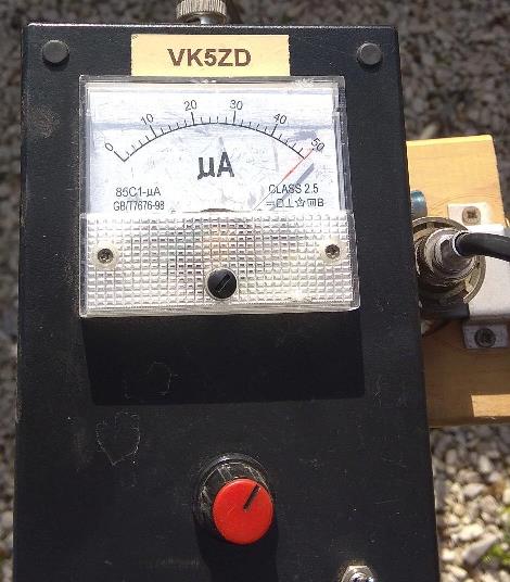
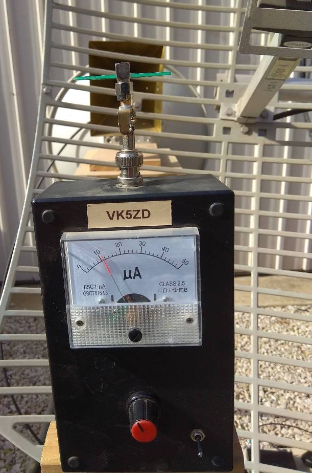
The detector is adjusted to give a full scale reading. |
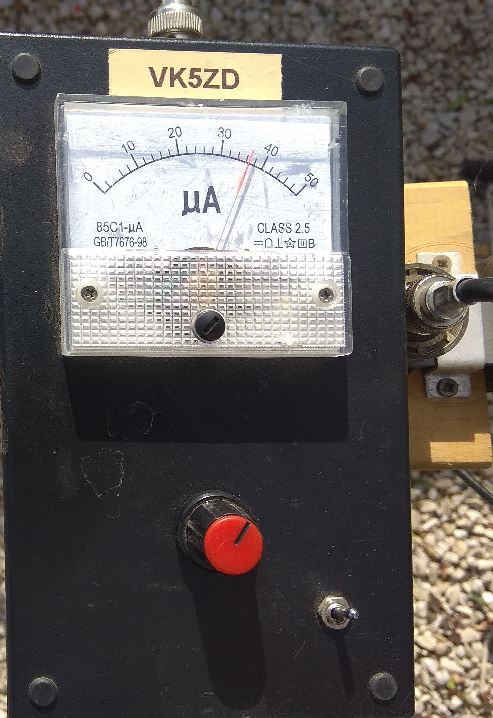
The reading with the grid antenna in the path.
|
The next set of images show the result at 10GHz.
|
|
 |
|
 |
 |
|
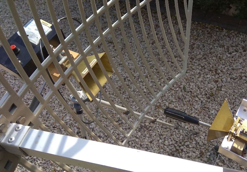
This is the
10GHz test setup. The RF source is on the right (Gunn
oscillator) and an old HP diode detector is on the left.
|
The detector is adjusted to give a full scale reading. |
This is the reading with the grid antenna in the path.
This voltage reading would suggest that 50% of the power is
coming through. |
|
| HOME |