
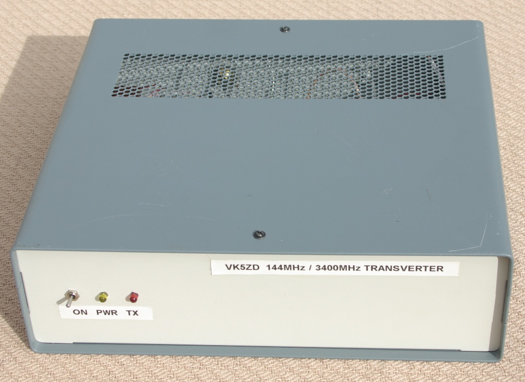

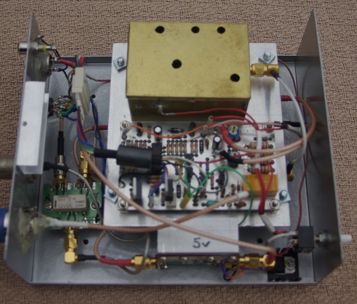
This 3.4GHz transverter uses a W1GHZ design shown here.
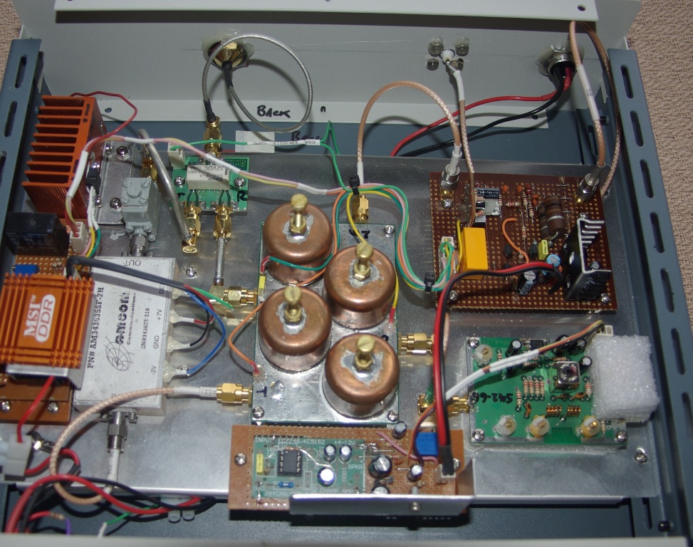
The transverter board can be seen in the centre of the chassis with the four pipecap
filters. The veroboard at the right-rear has the interface to the 144MHz I.F. radio, T/R switching and 8v regulator for the transverter. Right front is
a Minikits local oscillator. The crystal is inside the foam with a QH40A heater from Kuhne (surplus from my 10GHz transverter after I bought the
MKU-XO1-PLL). The output frequency from this board is 542.6667MHz. Centre front is the power supply for the local oscillator. To keep things as
stable as possible, I decided to provide a regulated 12v supply.Since this unit runs from a 12v battery, I need to boost the voltage up so it can be
regulated back to 12v. This is done using a half watt audio amplifier kit from Jaycar called 'The Champ'. The circuit was altered to be a square
wave oscillator with the output being rectified and added to the nominal 12v battery supply. This gives around 17v which then goes to a LM317
regulator. To the left of the transverter board is a commercial 4 watt power amplifier which is connected to the antenna changeover relay via an
isolator. On the left of the chassis is the power supply for the PA which requires a -2v bias supply and +7v at 2.5A.
This 10GHz transverter is built around the VK3XDK kit. On the right in the picture is a phased locked oscillator with an output frequency of
2,484MHz. This is referenced to a 10MHz OCXO in the centre of the chassis. The two boards supplied with the kit are mounted vertically, with the
multiplier board being closest to the oscillator. I added a plate with RF absorbing foam between the two boards. I doubt that this was actually
necessary but I figured it couldn't do any harm. Right front is a commercial Avantek 200mW amplifier. The strange looking device just above it is
my attempt at a home brew attenuator. Centre front is the antenna changeover relay. Left front is a switch mode supply used to produce 28v for
the relay and a regulated 12v for the PA. Left rear is the I.F. radio interface and T/R switching, all controlled by a PICAXE-08M chip.
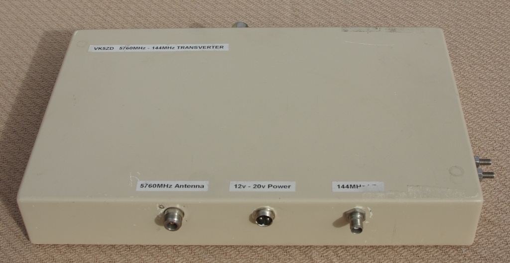
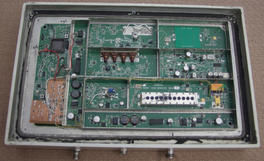
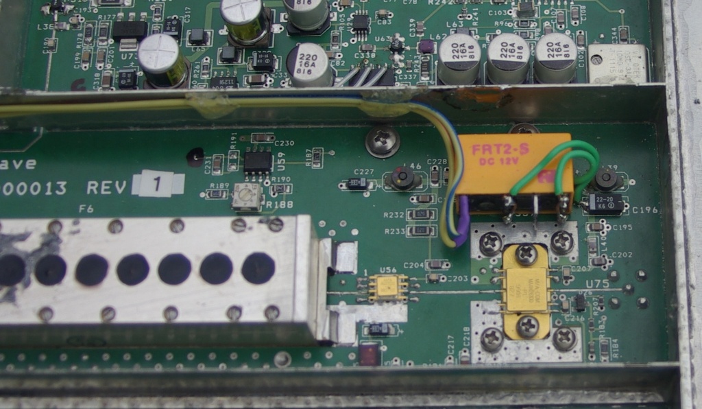
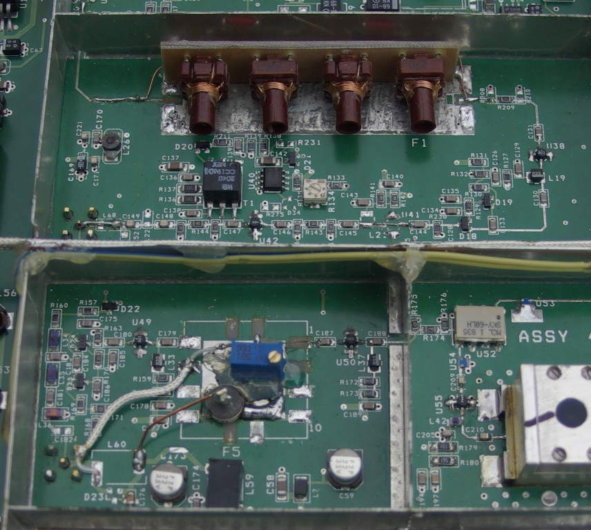
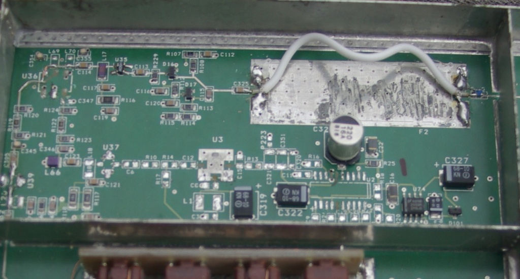
This is a commercial 5.8GHz data link that has been converted to a transverter. The unit was made by a company called ioWave. Originally, it
used a full duplex system with Tx and Rx frequencies 60MHz apart. The transmit site used a single mixer to convert the incoming signal on
110MHz up to the output in the 5.8GHz band. The receive side used dual conversion with a first I.F. of 170MHz and a second I.F. of 70MHz.
Both local oscillators used VCOs phased locked to an internal 10MHz TCXO.
To convert it to a transverter, the processor was removed and replaced with a PICAXE-08M chip which does the T/R switching and programs the
PLL for an I.F. of 144MHz. The second receive mixer was removed and the original 70MHz filter replaced with a home brew version for 144MHz.
Not visible in the photos (underneath the PCB) is a 28v power supply and antenna changeover relay.
The receiver is very sensitive and the transmitter produces about 750mW of output. The only problem is the relatively high level of phase
noise from the local oscillator which produces a quite noticable hiss on what should be full quieting FM signals.
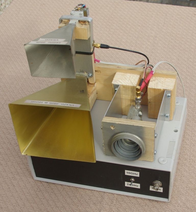
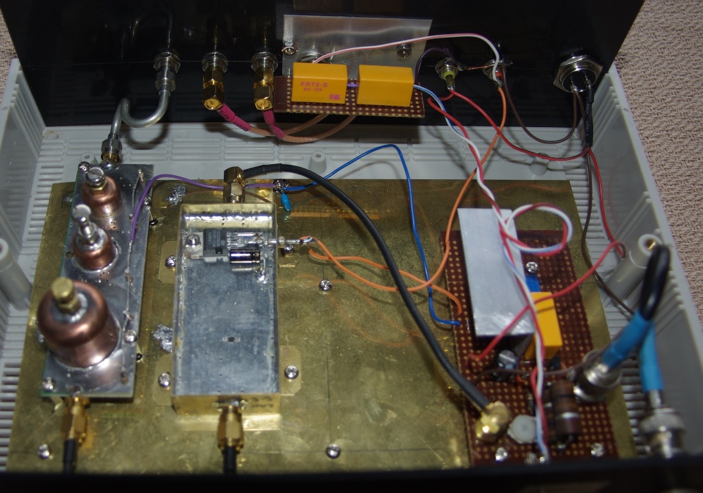
WBFM system for 10GHz and 24GHz. An old LNB is used for the 10GHz receiver with the output being fed to a Uniden scanning receiver (not
shown). The transmitter takes a signal on 425MHz from my FT-60 H/T. This is fed to a Minikits 3.4GHz multiplier which does a x8 to
produce 3,400MHz. This then goes to a W1GHZ '10GHz Personal Beacon'
board which outputs 10mW on 10.2GHz. The 24GHz system uses a conventional gunnplexer arrangement. The unit has a switching arrangement
to connect the scanning receiver to either the LNB or gunnplexer outputs. For such a simple system it has produced surprisingly good results.
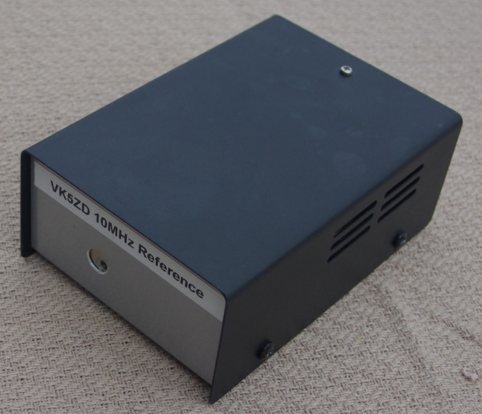
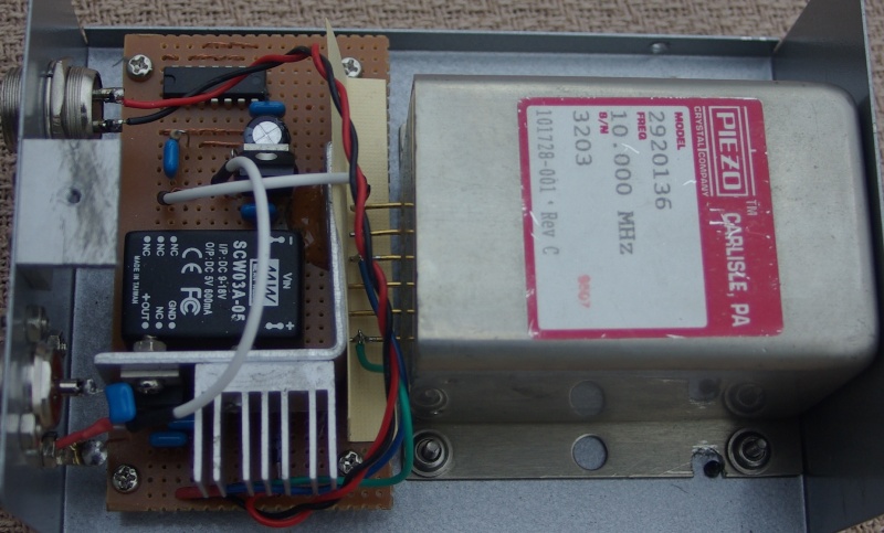
This is a high stability 10MHz oscillator I usually use with my DB6NT 10GHz transverter. The frequency accuracy is more than adequate
for voice communications.
WORKS IN PROGRESS...
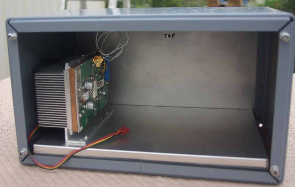
Transverter for 1296MHz. The picture on the right is of a Minikits transverter which a built some years ago. I'm going to move it to the
larger box with the addition of the 60 watt PA stage visible in the left hand picture.
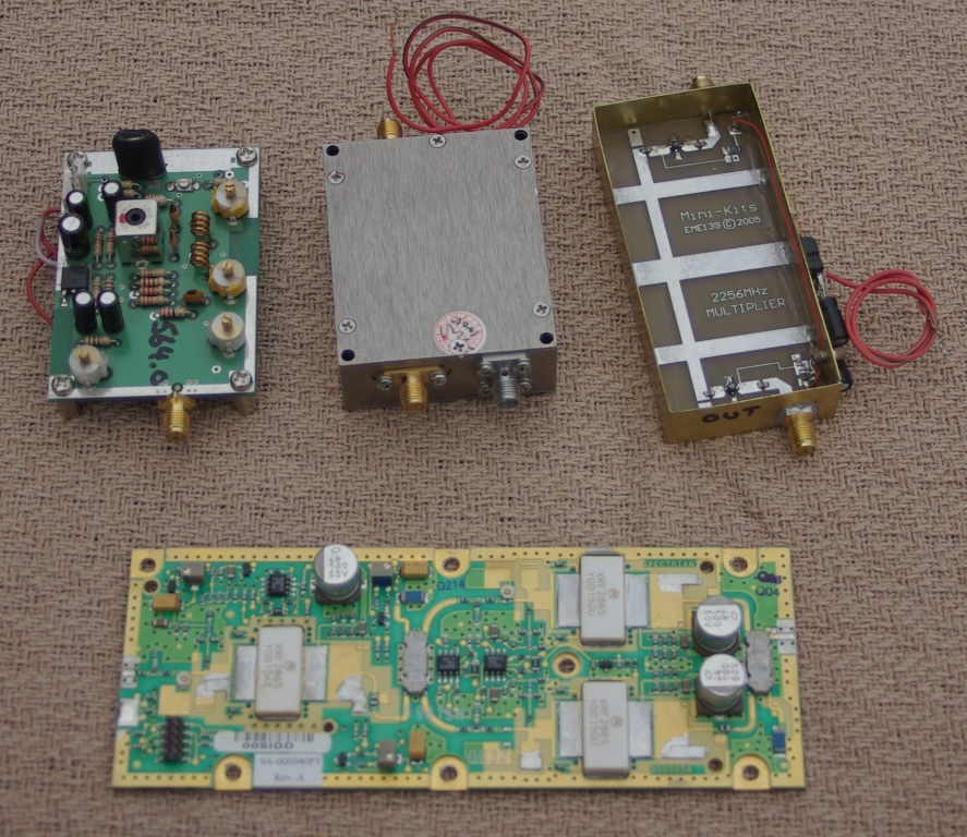
Parts for a second 2.4GHz transverter. Minikits oscillator and multiplier, commercial receive converter and a ~70 watt Spectrian PA board.
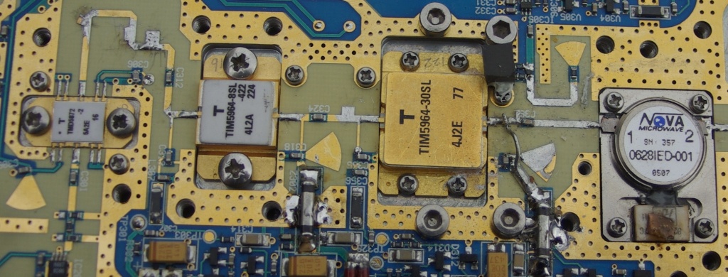
Surplus commercial PA which, I am told, should produce around 20 watts output at 5,760MHz.