This filter is designed to remove interference caused by pager transmitters operating between 148MHz and 150MHz.
They are in effect cavity resonators constructed from LCF158 coaxial cable.
Specifications for this cable can be found here.
This is some serious coaxial cable. It has a 50mm outer diameter and very low losses (0.82db/100m @ 150MHz).
Both the outer and inner conductors are mode from solid corrugated copper.
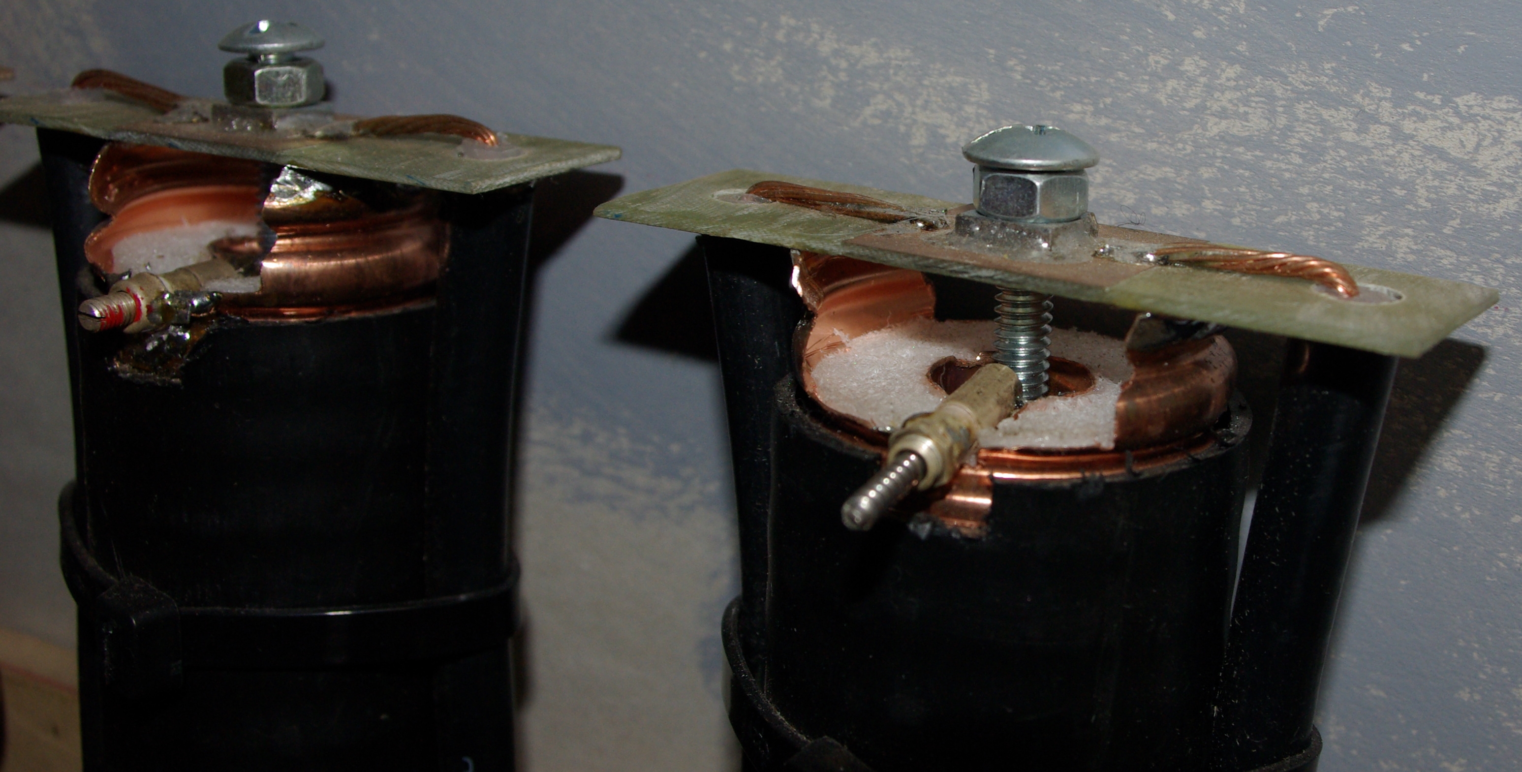
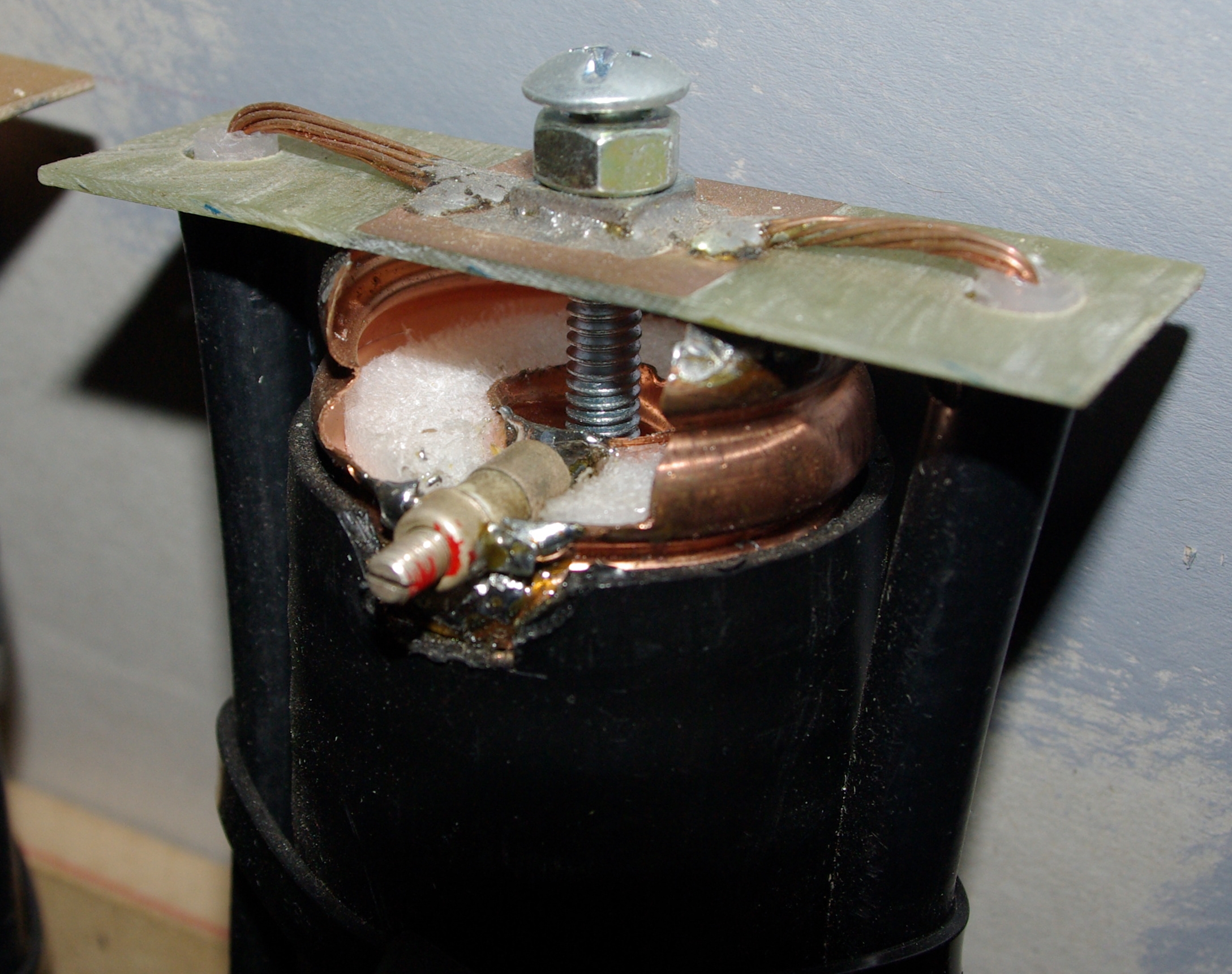
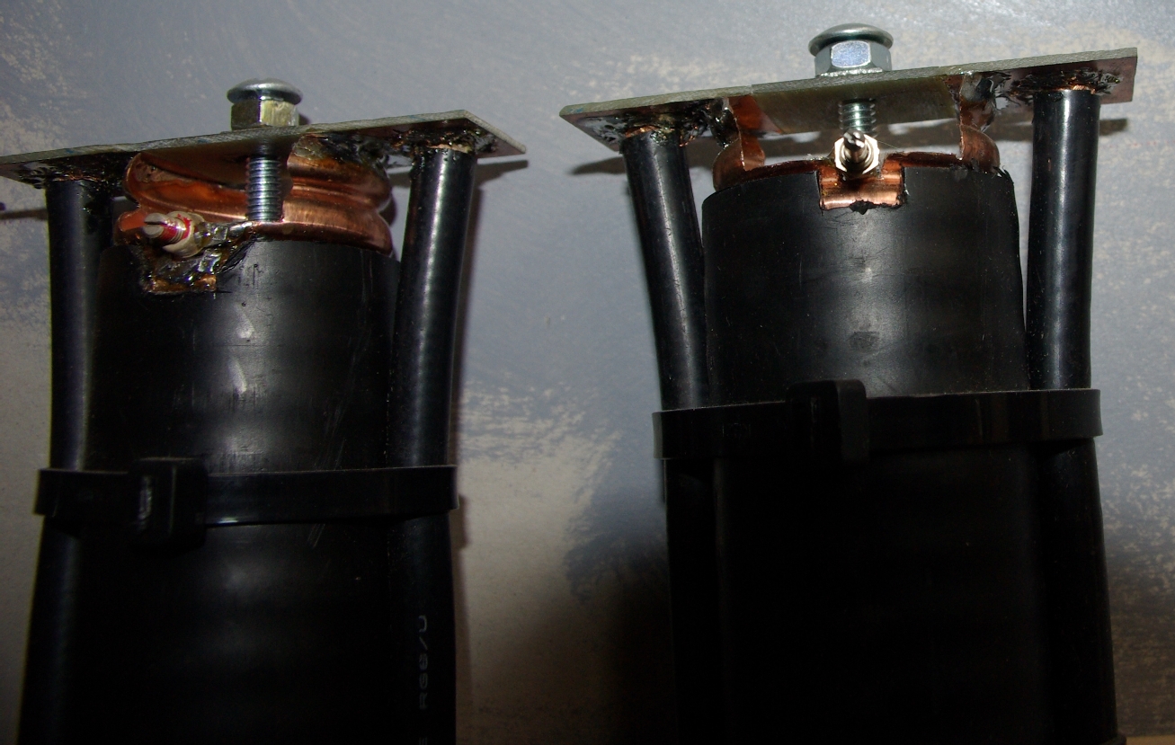
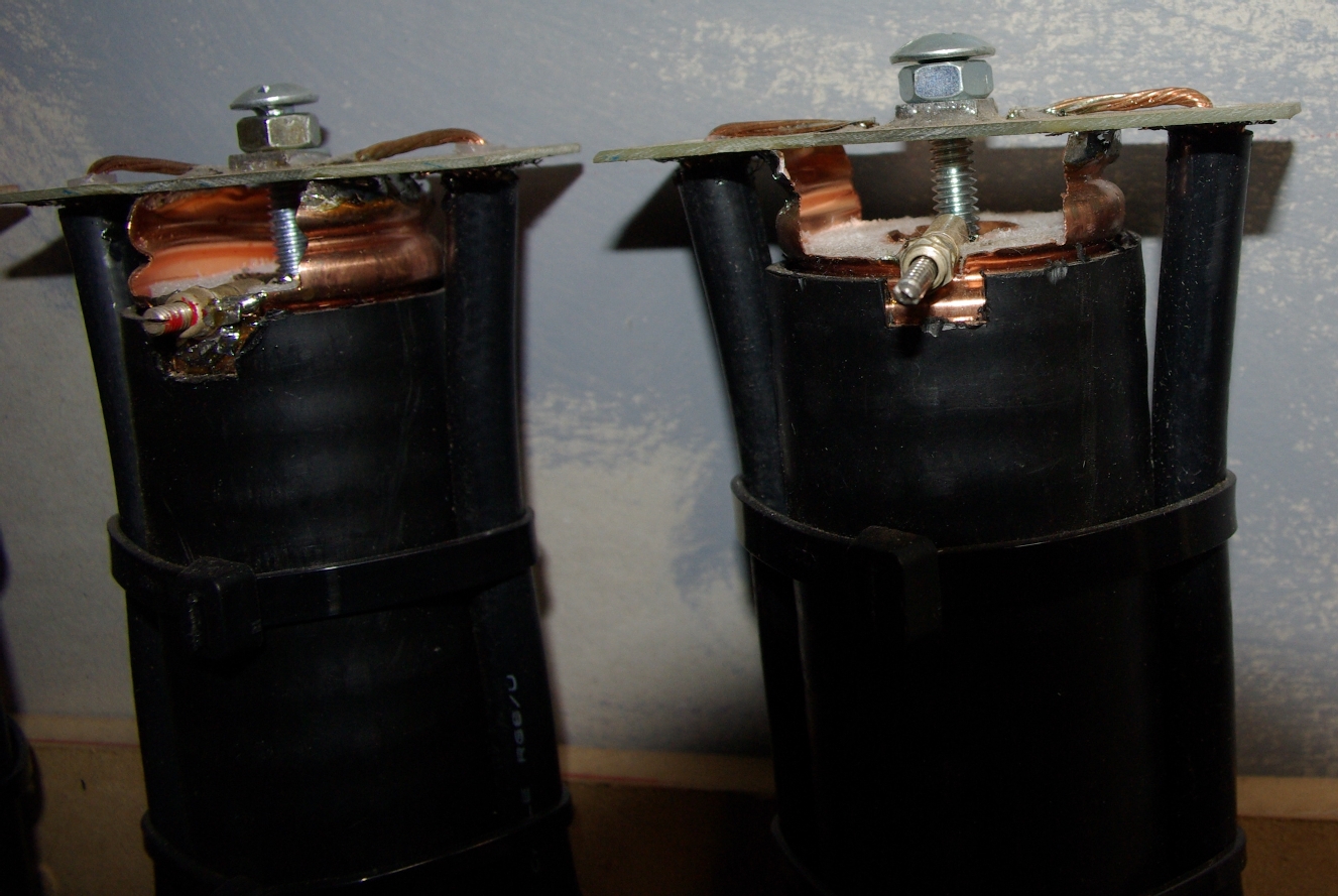
The first three images show a test model.
The bottom is shorted by soldering either a piece of PCB or 16 copper wires between the inner and outer conductors.
The section of LCF158 is 41cm long. The bolt in the top is 60mm long (threaded section, 65mm total including the head).
The actual size is not critical. There is a nut soldered to a piece of PCB that sits across the top of the LCF158
supported by two smaller pieces of PCB soldered to the outer copper shield. Copper is removed from the PCB so there
is no connection between the bolt and the LCF158 shield.
Click on the pictures to view hi-res images.
The following images show the frequency response of the test model over various frequency ranges. The vertical scale is 10db per division.
Image 1  Image 2
 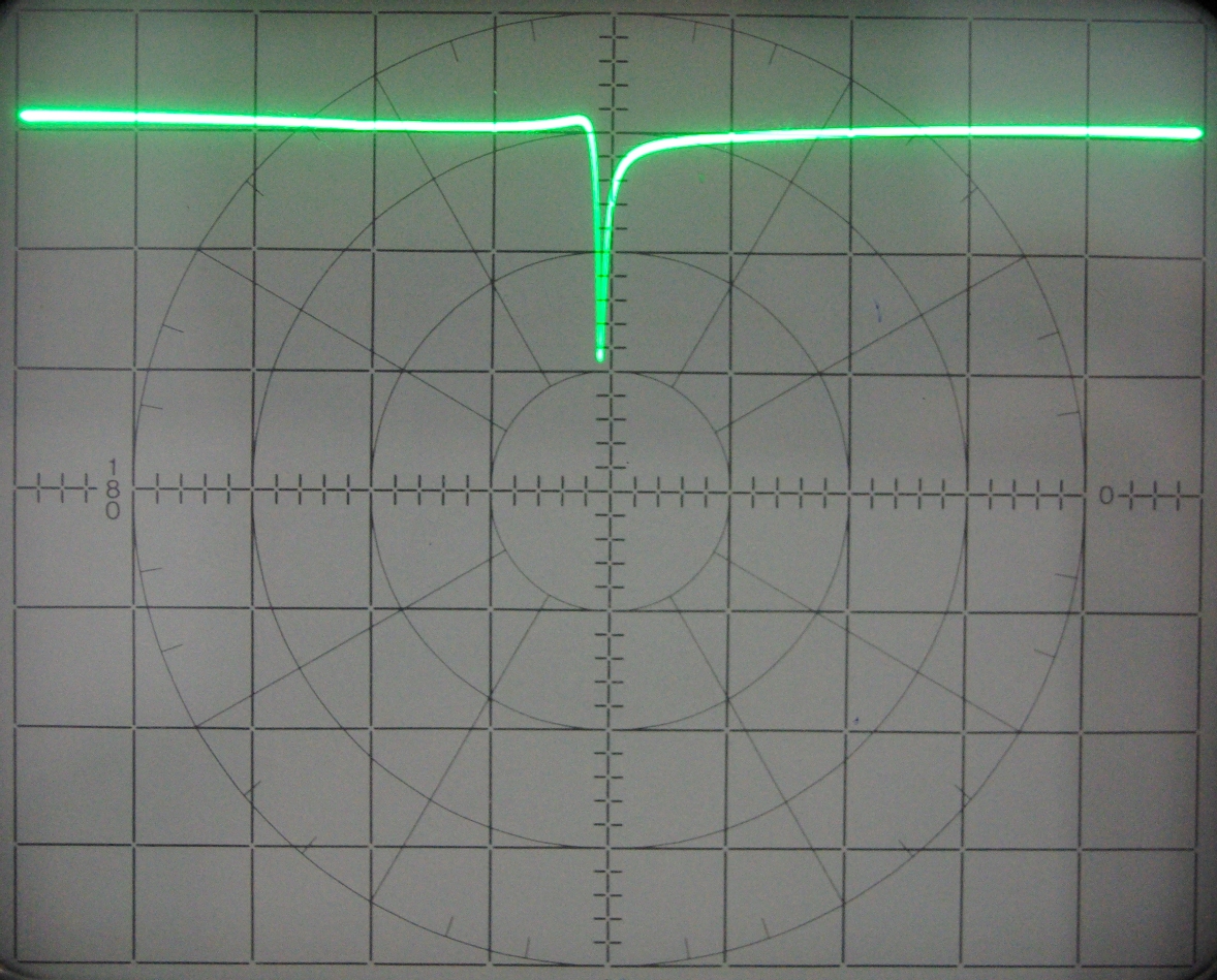 Image 3
 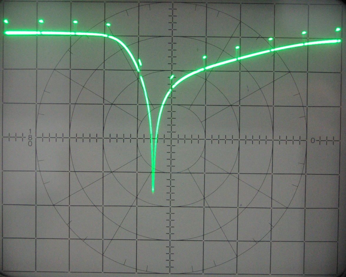 Image 4
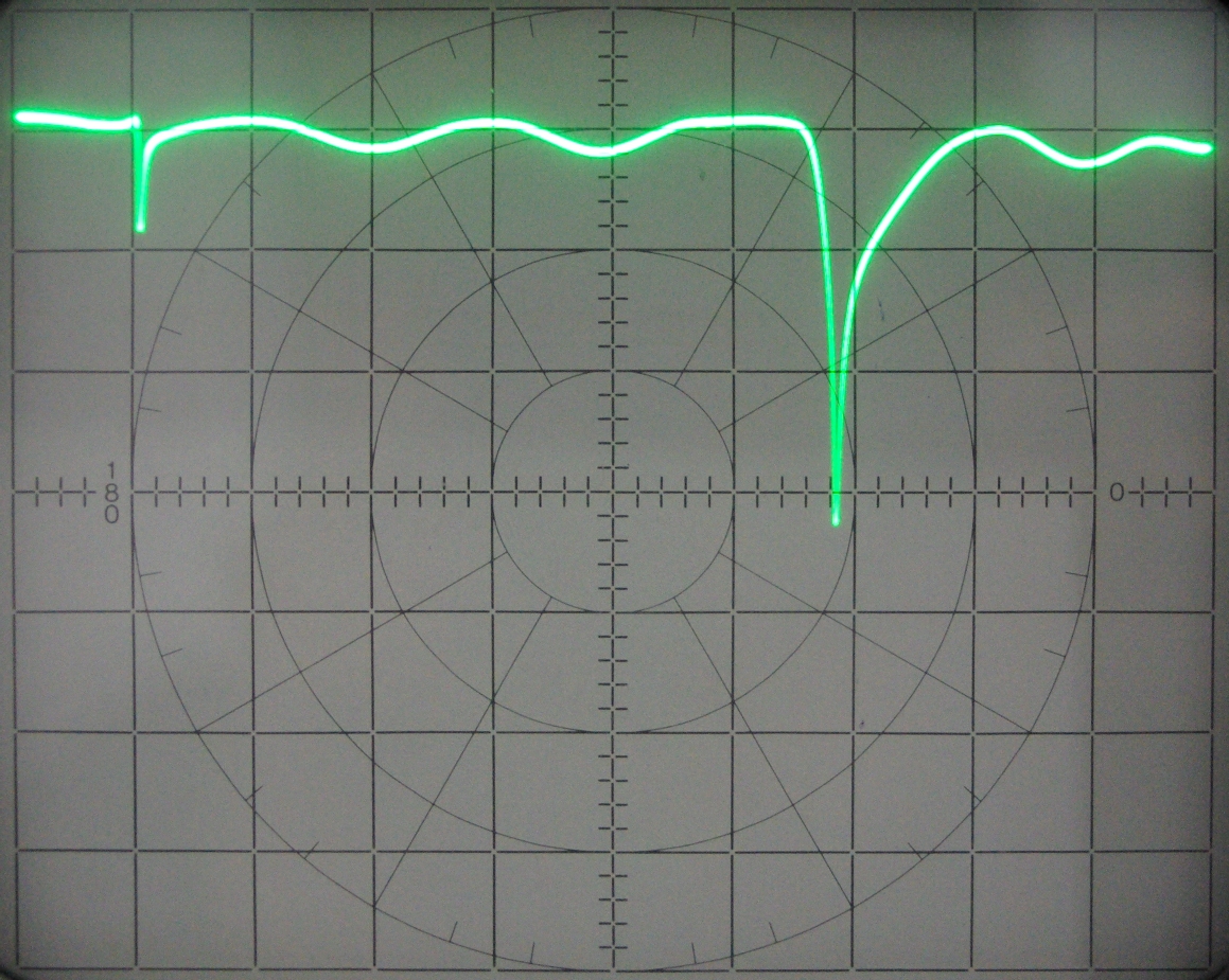
Image 1 shows the response between 145MHz and 150MHz (markers at 1MHz intervals). The notch depth is almost 30db.
The attenuation starts at 147MHz, reaching 10db at 148MHz with the maximum attenuation occuring at about 148.25MHz.
Image 2 shows the response between 125MHz and 175MHz. Aside from the notch, there is almost zero insertion loss.
Image 3 shows the response between 400MHz and 500MHz (markers at 10MHz intervals). The notch here is at the 3rd
harmonic frequency. The depth of this notch is about 46db. Note that the attenuation starts at about 430MHz and reaches
about 12db at 440MHz.
Image 4 shows the response between 100MHz and 600MHz. Note there is about 3-4db of ripple in the pass band.
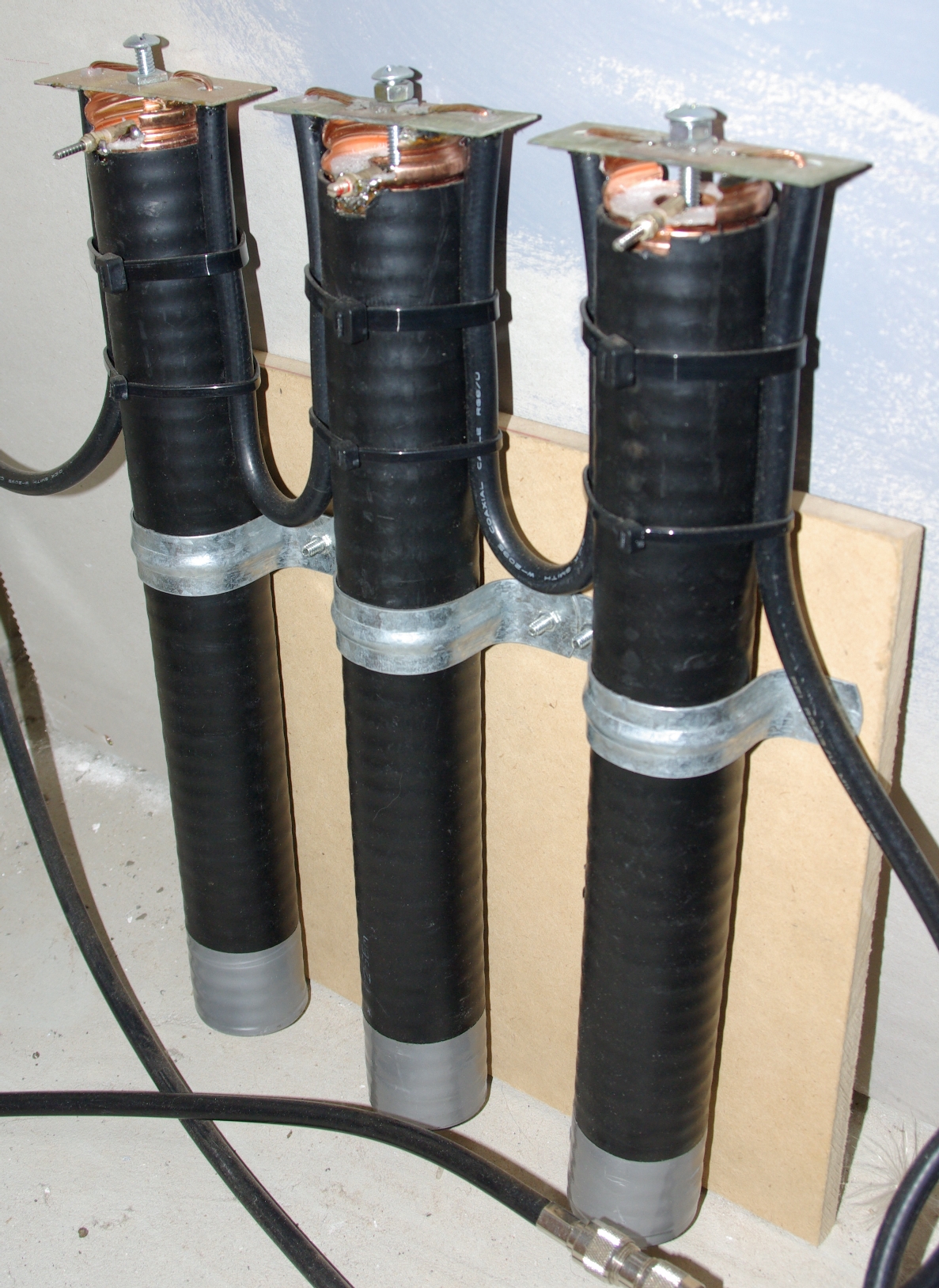
The next set of images show the final version which is made up of three filters in series. In my case, I'm using the filter
on a Yaesu FT-8900 with a single antenna. This meant that the notch in the 70cm band should not attenuate frequencies up to
440MHz. To do this, I reduced the length of the LCF158 and tuned it using a 5pf trimmer capacitor soldered between the inner
and outer of the LCF158 at the top. This has the effect of moving the 70cm notch higher in frequency (the attenuation starts
at about 440MHz). Adjustment is also simpler with this design.
For this version, the length of the LCF158 inner conductor is 39cm. The two sides of the out conductor were left 20mm longer
to provide a support for the PCB.
Adjusting either the trimmer or the bolt changes the notch frequency. The length of the bolt also affects the depth and width
of the notch. The bolt should be adjusted to set the size of the notch and the trimmer used to move it on to the desired frequency.
The cables connecting the filter sections are 1/4 wavelength (500mm x Velocity Factor). This reduces the influence of one
filter on the next when making adjustments.
HOME