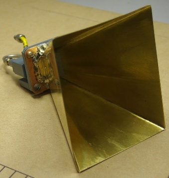
This horn antenna, with a theoretical gain on 18db, is for 10GHz.
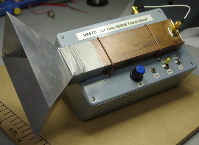
This was device was contructed for use in a VHF/UHF field day contest. It's a wide-band FM system based on an A/V sender. Not a lot of TX power (+10dbm) or receiver sensitivity, but, with the 15db gain horn antenna, good enough for short range contacts with a second, similar device. The A/V sender I used has a choice of 4 frequencies, 3 of which are withing the amateur allocation.
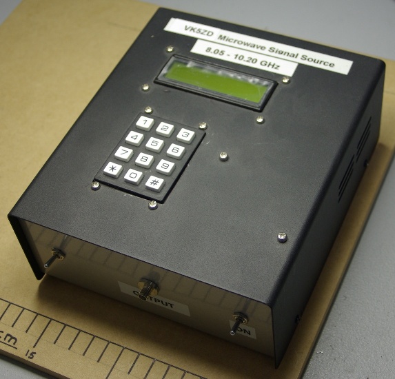
I built this device around one of the Stellex YIG oscillators that appear quite regularly on eB@y. A Picaxe chip is used to program the PLL, with the desired frequency being entered on the keypad. Since this picture was taken, the YIG oscillator has been replaced with one that covers 9.4GHz to 10.6GHz.
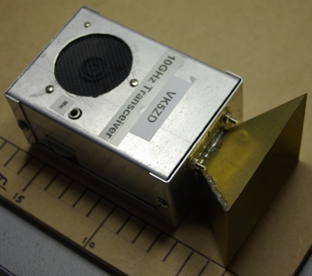
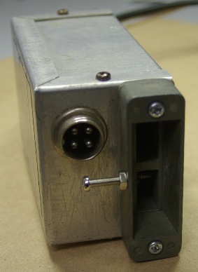
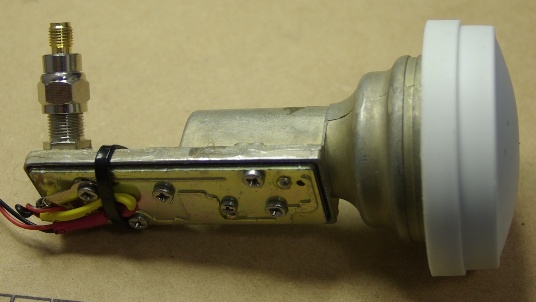
This is a 10GHz handheld tranceiver that was contructed for use in a VHF/UHF field day contest. The only bits that aren't in the box are the microphone and 12v battery. It is a simple WBFM system using a Gunn oscillator and the board from an FM 'tranny' as the receiver I.F.
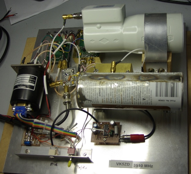
Another WBFM transverter operating on 3510MHz that was contructed for use in a VHF/UHF field day contest. The receiver uses a C-Band LNB. The transmitter output (+10dbm) is from the length of circular waveguide (ex spray paint can) in the centre. It is based on a Minikits ATV board with the PLL option. When receiving, this generates a 1250MHz signal. Since the LO in the LNB is 5150MHz, the output from the LNB is 1640MHz (5150 - 3510). This is mixed with the 1250MHz to produce and I.F. of 390MHz which is fed to a Uniden scanner set to WBFM. On transmit the ATV board produces an FM signal on 1170MHz. This is fed to a tripler (also from Minikits) to produce the output frequency of 3510MHz. In one test I was able to receive a signal from an identical system over a line-of-site range of about 85km (only managed one way). I found this quite remarkable when you consider that there is no antenna gain to speak of.
10GHz Gunn oscillator #1. This was constructed for WBFM experiments back in 1988. Output power is about +7dbm.
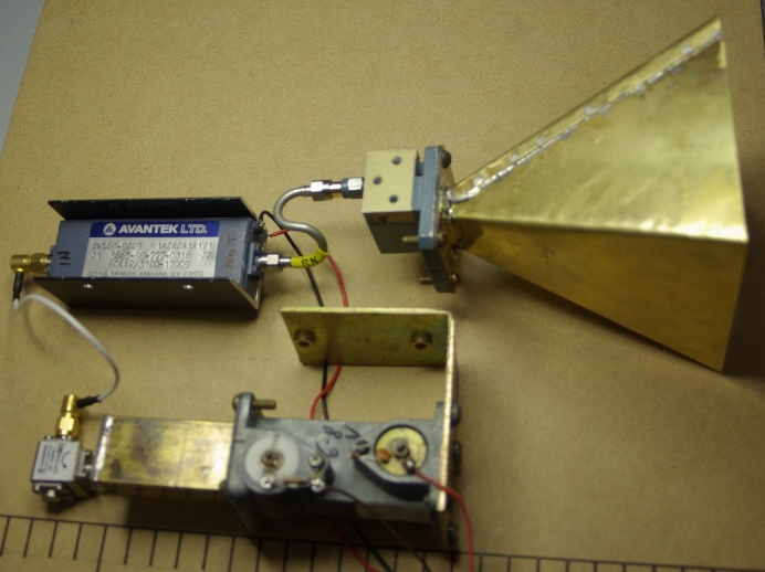
An experimental setup. Gunn oscillator --> home made waveguide to coax adapter --> isolator --> amplifier (+23dbm output) --> horn antenna.
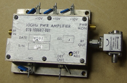
10GHz amplifier for future use. Output is >+33dbm (2 watts).
Modified Ku band LNB. The high-pass filter on the IF output has been removed (hence power no longer goes via the coax) and the strip-line filter on ~11GHz between the RF amplifiers and the mixer has also been removed (replaced with a straight connection). I conducted a simple experiment with this device. The 10GHz Gunn oscillator #1 was fixed to my antenna mast (with duct tape) and powered up. It would have been about 5m above ground level and pointing roughly west. The output frequency is ~10290MHz frequency modulated with a tone of about 400Hz. I then connected the LNB to a scanning receiver, put this in the car and drove off. I was able to find 2 line-of-sight locations at 5.5km and 6km from my QTH where the signal was easily received (almost noise free). The devices were as you see them in the pictures (no additional antenna gain).
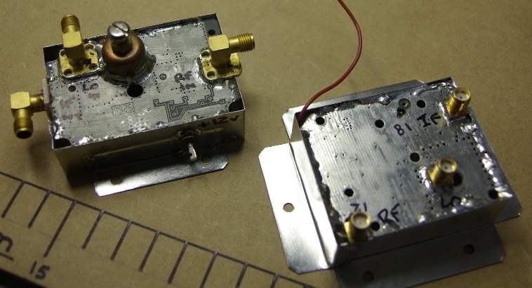
Another couple of modified LNBs, Ku band on the left and C band on the right. Both of these have the dielectric resonator for original LO removed so the mixers can be fed from an external source.