Notes on the DB6NT 10GHz Transverter - Part 2
Home Part 1 Part 2 Part 3 Part 4
|
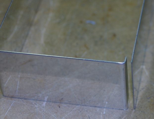
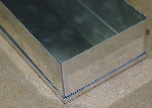
The instructions begin by getting you to assemble the sides of the tinplate box.
You must get the overlap correct or the PCB won't fit. This image shows the correct way to overlap the edges. |
|
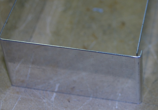 |
This is the incorrect way to overlap the edges. If you do it like this the PCB won't fit! |
|
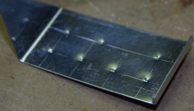 |
The instructions tell you to solder the sides of the box together before you mark
and drill the holes. I found it easier to do this before soldering up the
box. I was having a senior moment when I did this; it's easier to drill if you mark and punch the outside. |
|
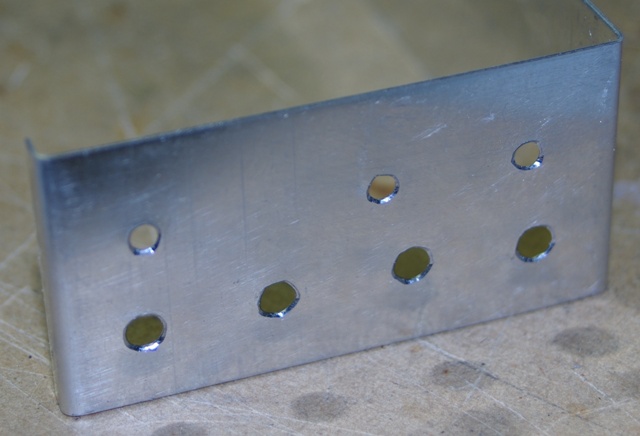 |
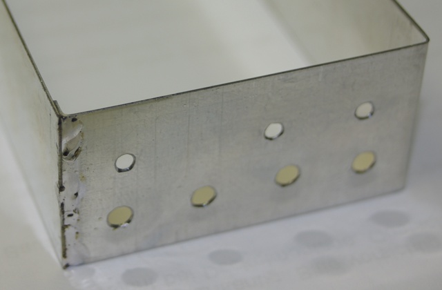
I drilled 3.5mm holes for the SMA connectors and feed-through capacitors. I used a 1.5mm drill for the SMA connector screws. Note: You will need to tap the holes (M2 size). If you just try to force the screws in you will strip the threads (the tinplate is quite hard). I drilled the screw holes later after the PCB was fitted. I soldered the connector to the PCB so I could mark exactly where the holes needed to go. |
|
 |
I placed the sides into the top cover to hold everything in the correct position
for soldering. |
|
 |
After soldering the sides together. | |
HOME Part 1 Part 2 Part 3 Part 4