Notes on the DB6NT 10GHz Transverter - Part 3
Home Part 1 Part 2 Part 3 Part 4
|
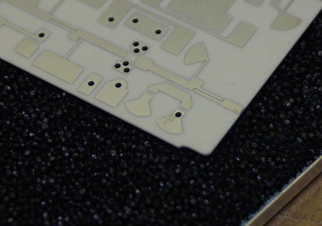
The instructions tell you to trim the PCB to fit the box. The corners need
to be cut to fit round the joins in the box as shown in the picture. I also
had to reduce the length of the board by about 0.5mm so it would fit. Note that the the board material is very hard. A normal metalworking file will have little effect. I used a Dremel tool with a cutting disk to trim the board. |
|
 |
I first tacked the PCB into the box. I supported the board on a piece of metal
of the correct thickness (10.5mm). Check that the SMA connectors can be positioned correctly before proceeding. * Note * Contrary to the instructions, some of the components are easier to fit prior to soldering the board into the box. See Part 4. |
|
 |
Once I had verified that the PCB was correctly positioned in the box the soldering was completed. | |
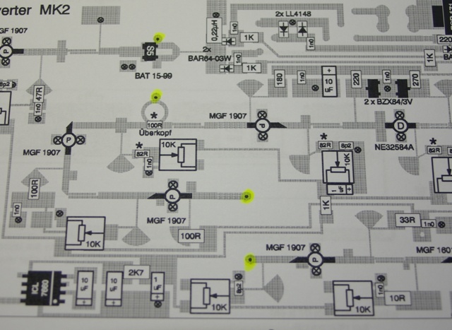 |
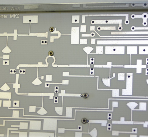
The next step is to fit the pipecap filters. The highlighted points in this image show where the probe pins should be fitted. | |
 |
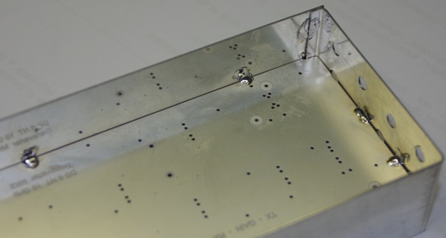
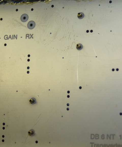
This shows the underside of the PCB after fitting the probe pins. | |
 |
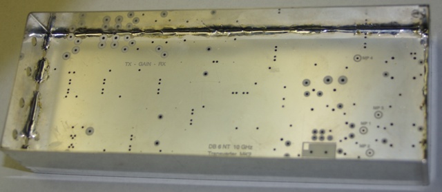
This image shows the probe pins from the top side of the PCB. They don't protrude very much. | |
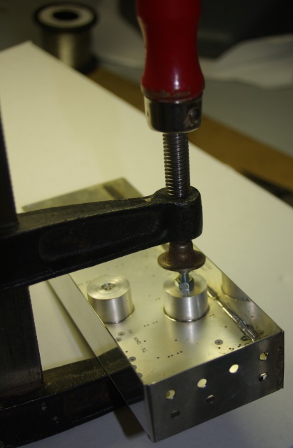 |
The instructions tell you to tin the bottom of the resonators, fit a short M4 screw
in the top then heat the screw with a soldering iron. If you adopt this method
you will need a big soldering iron. It was beyond the capabilities of my 60w Weller so I used a different method. I coated the bottom surface of the pipecap with solder paste and then held it in position with a clamp as shown in the image. There is a small piece of wood between the clamp and the underside of the PCB and I fitted a temporary M4 screw in the top. The pipecap was the heated with a small gas blowtorch until the solder paste melted. |
|
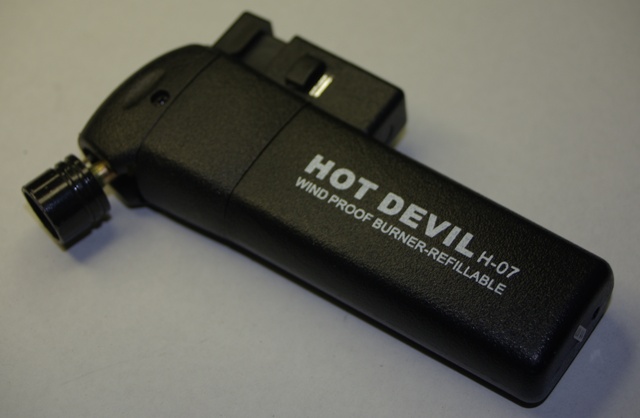 |
This is the gas blowtorch I used. It's not very big. Basically, it's
a disposable cigarette lighter with a piezo igniter and a fancy burner. |
|
HOME Part 1 Part 2 Part 3 Part 4