Notes on the DB6NT 10GHz Transverter - Part 4
Home Part 1 Part 2 Part 3 Part 4
|
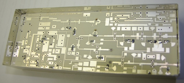
Contruction in progress. Only a few SMD resistors and capacitors have been fitted at this stage. | |
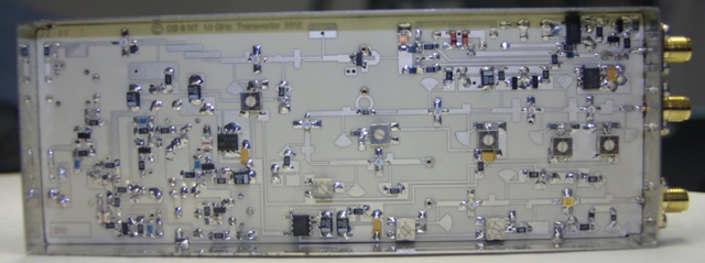 |
All the components have now been fitted except for one 1pf capacitor which mysteriously
dematerialised from the end of the tweezers when I wasn't looking. A replacement
is enroute to my QTH. |
|
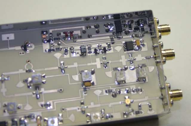 |
Note that the centre pin on the SMA connectors should be cut back to the minimum
length necessary to solder them to the PCB (see picture in the instructions). It would be easier to fit the components in the corner next to the IF input before the PCB is soldered into the box. There's not a lot of room to work once the PCB is in the box. |
|
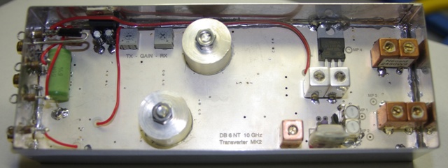 |
A top side view of the completed transverter. | |
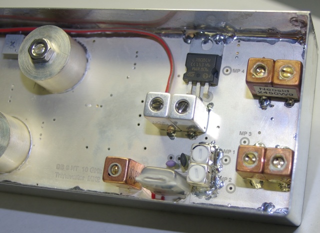 |
The instruction say to solder the components to the underside first. If you
do this there is a danger that you may cover the holes for the filter s with solder.
I suggest mounting the filters first. The instructions also show that the filter cans should be soldered to the PCB. This would also be a lot simpler if it is done before the PCB is mounted in the box. |
|
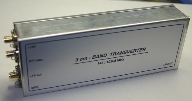 |
Finished !! | |
HOME Part 1 Part 2 Part 3 Part 4