Hello and welcome to my web site.
I've been playing with RF stuff since I was about 10 or 11 years old (thanks to my Dad who was working at Marconi Instruments at the time).
At age 13 we moved to Australia and I continued to play with things electronic. I obtained my AOLCP and first licence (VK5ZIJ) back in August
1969 while still at high school and have been playing ham radio on and off since then. My interest in the microwave bands started in the mid
80s and is still going. I now have transverters that enable me to operate on all bands from 1,296MHz up to 122GHz
73
Iain
Page Last Updated: 22 October 2018
225717 Visitors since 9/08/2009
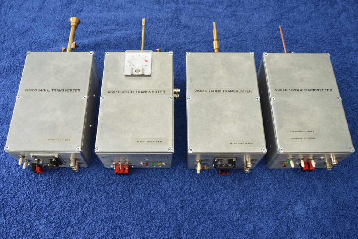
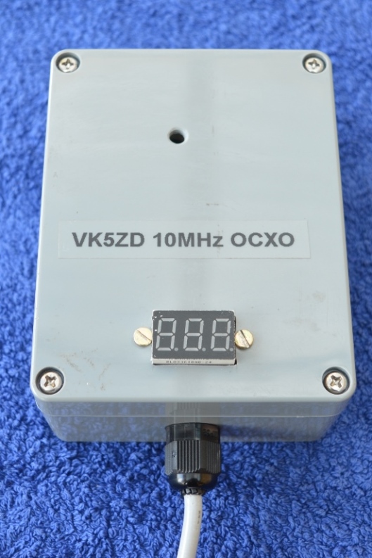
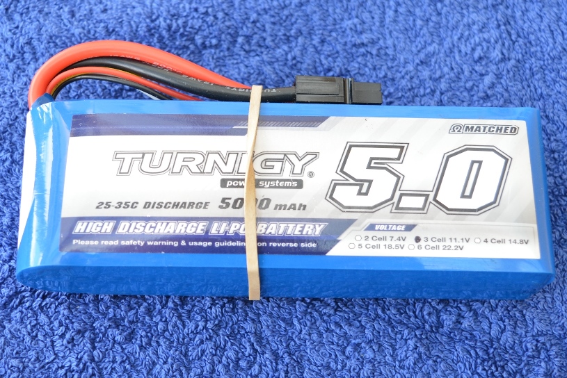
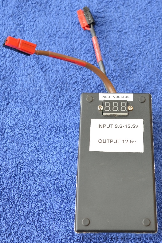
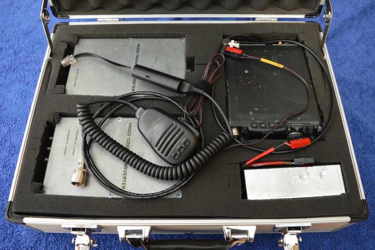
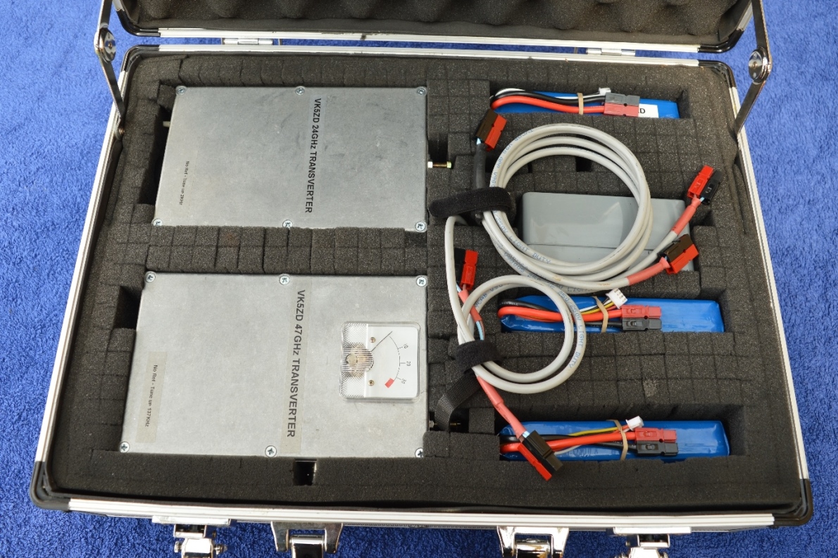
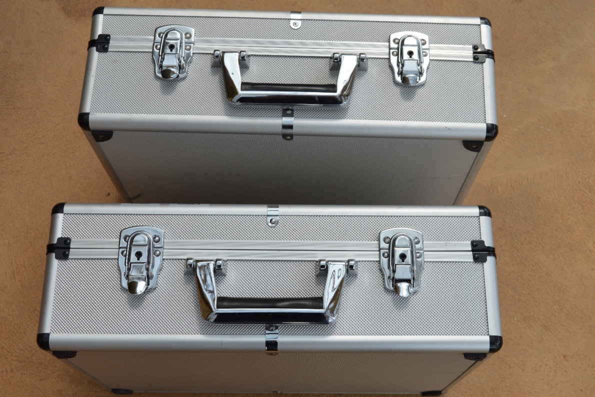
| 23 Sep 2019 | Some time ago I decided to build some portable transverters for the mmWave bands. The result (so far) is four units that operate on 24GHz, 47GHz, 76GHz and 122GHz. Each transverter is built in the same size die-cast box and they can be mounted in a common antenna. My I.F. radio of choice is the FT-817. The four transverters, the FT-817, batteries (3 x 5AH LiPo), a voltage regulator (providing 12.5v output), a 10MHz OCXO reference oscillator and various RF and DC cables fit into two small cases.
|
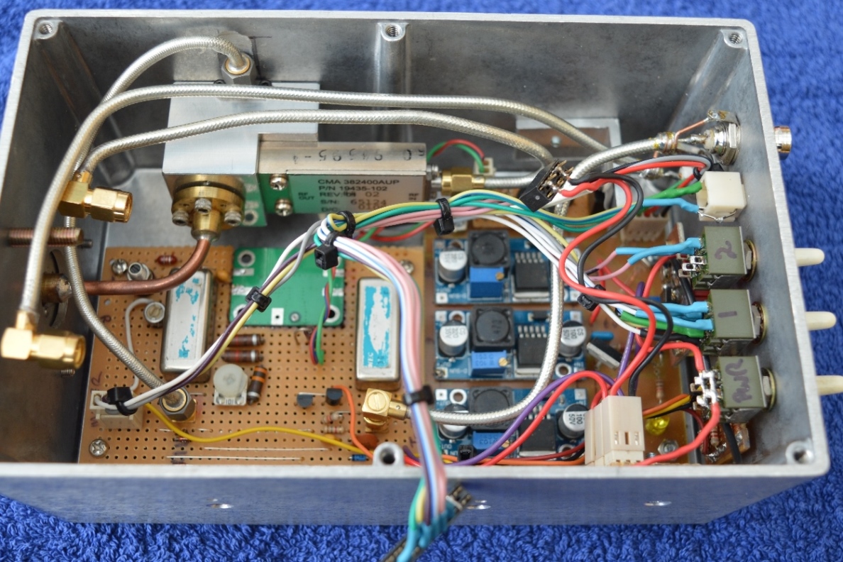
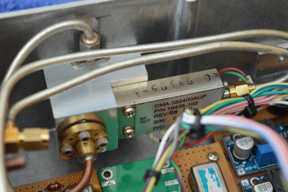
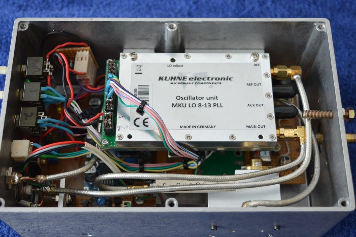
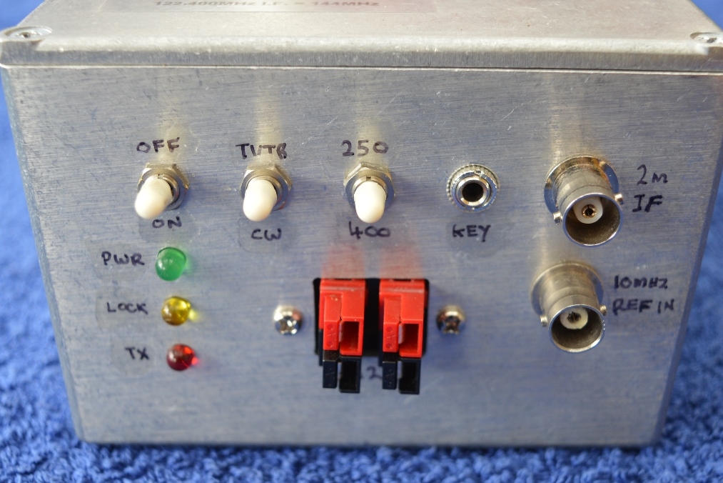
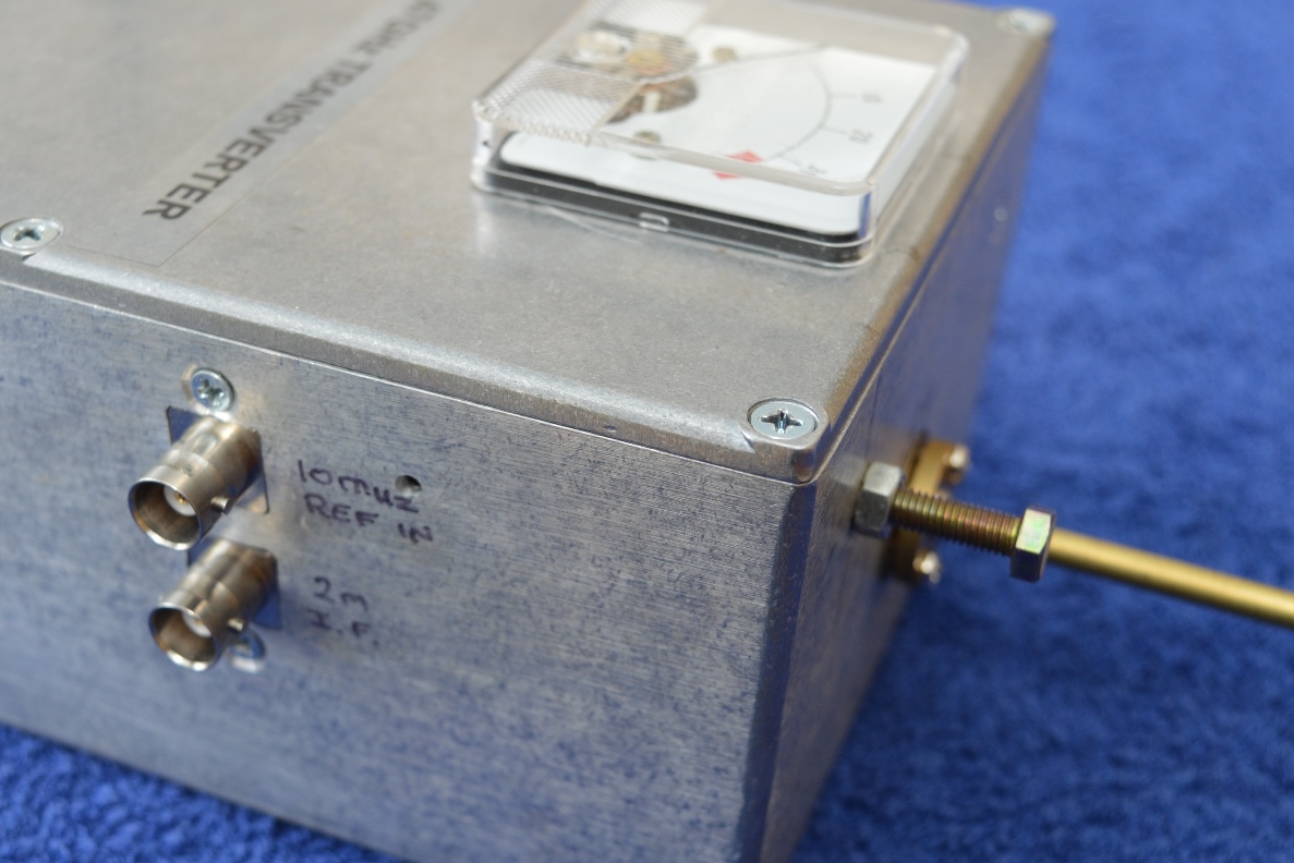
| 23 Sep 2019 | This is my 122GHz compact transverter. It uses a Macom MA4E310 GaAs Flip Chip Schottky barrier diode mounted in a housing from DL2AM. The LO is a Kuhne MKU LO 8-13 PLL set for 13,567MHz output. This feeds a CMA382400 tripler which gives an output of around 50mW on 40,701MHz. This, in turn, drives the mixer diode which, when mixed with the I.F. of 147MHz, gives a T/R frequency of 122,250MHz. There is also an option for a CW/beacon mode where the LO is set to 13,583.35MHz which, when mutiplied by 9, gives 122,250.15MHz. On transmit, this signal is about 10db greater than when mixing with the 2m I.F. frequency.
|
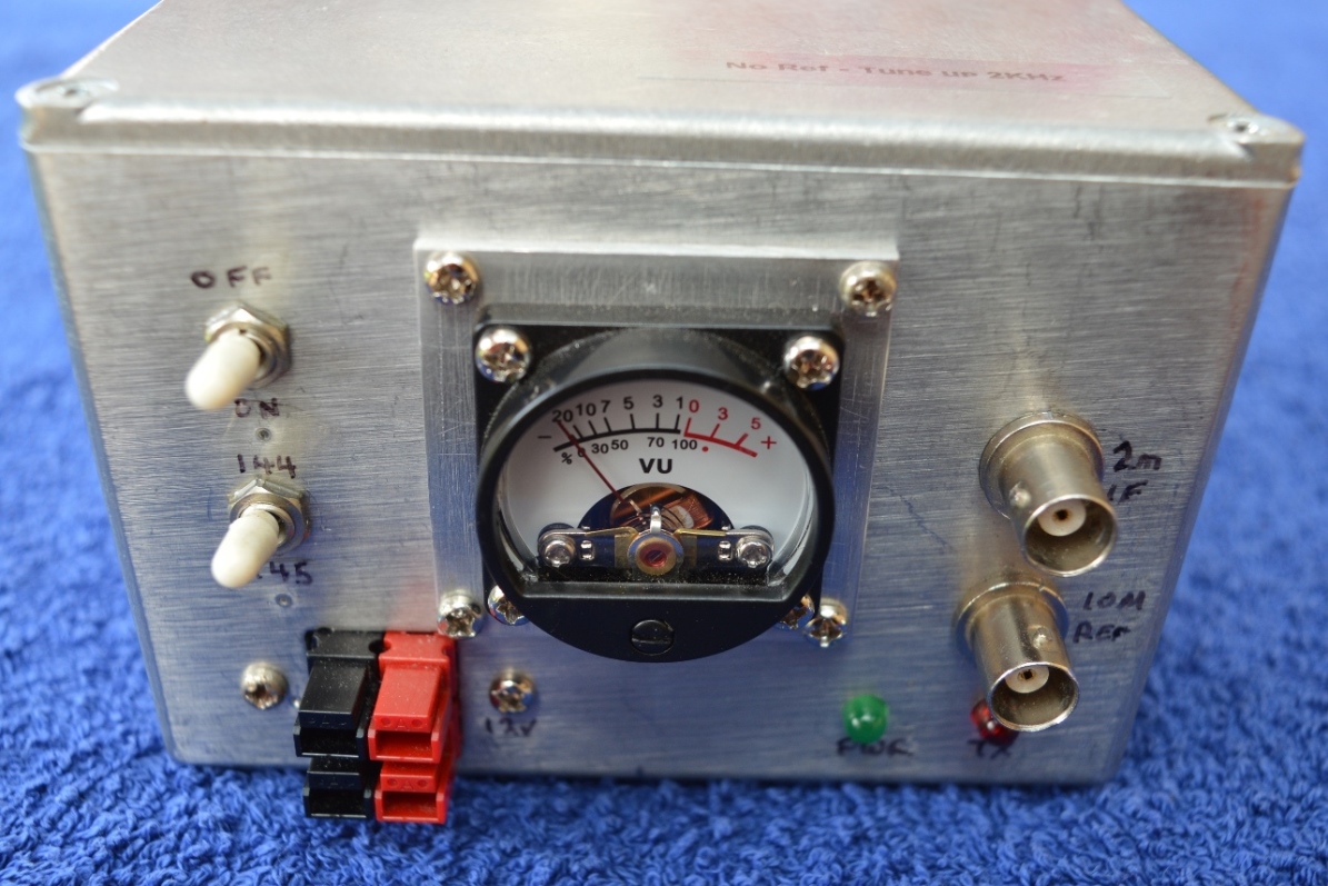
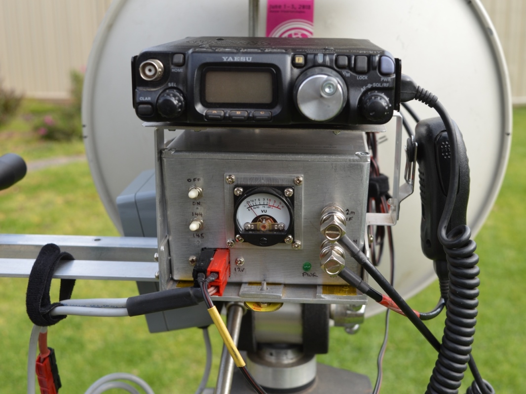
| 23 Sep 2019 | This is my 76GHz compact transverter. The transverter module is a Kuhne MKU 76 G2 (TX 250mW, RX 8.5db NF) and the LO is a Kuhne MKU LO 8-13 PLL. The antenna changeover relay and transverter control electronics were made by Rudi, OE5VRL and Hans, OE2JOM. The LO frequency can be changed by a switch on the front so the I.F. frequency is either 144MHz or 145MHz (for 76,032MHz). A small meter is connected to the monitor output of the transverter module to give an indication of TX power.
|
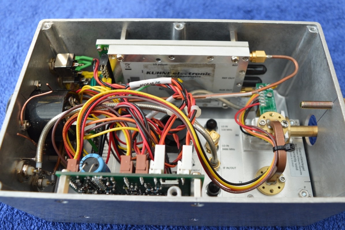
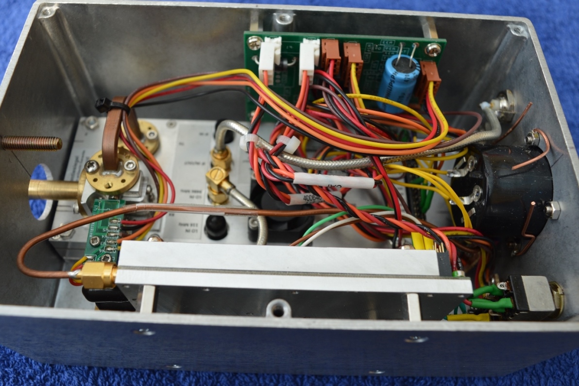
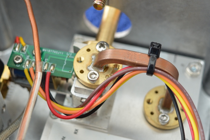
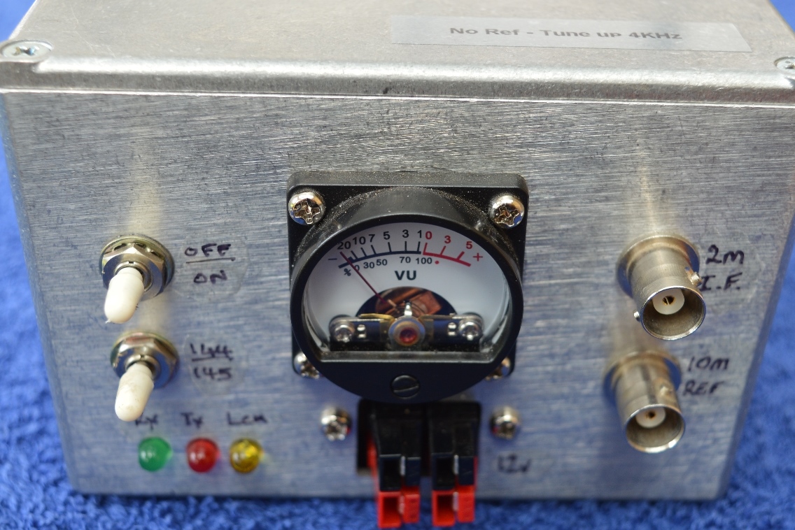
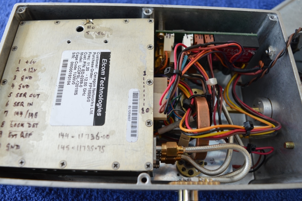
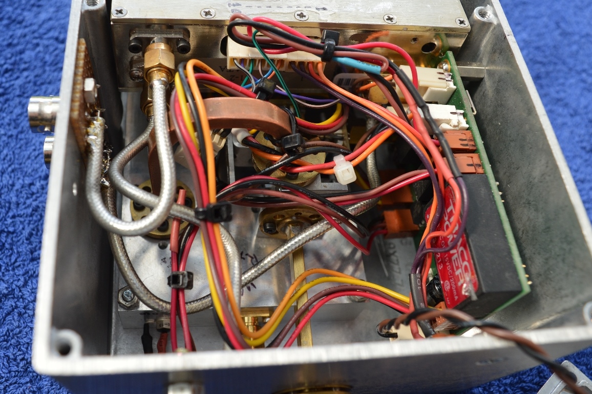
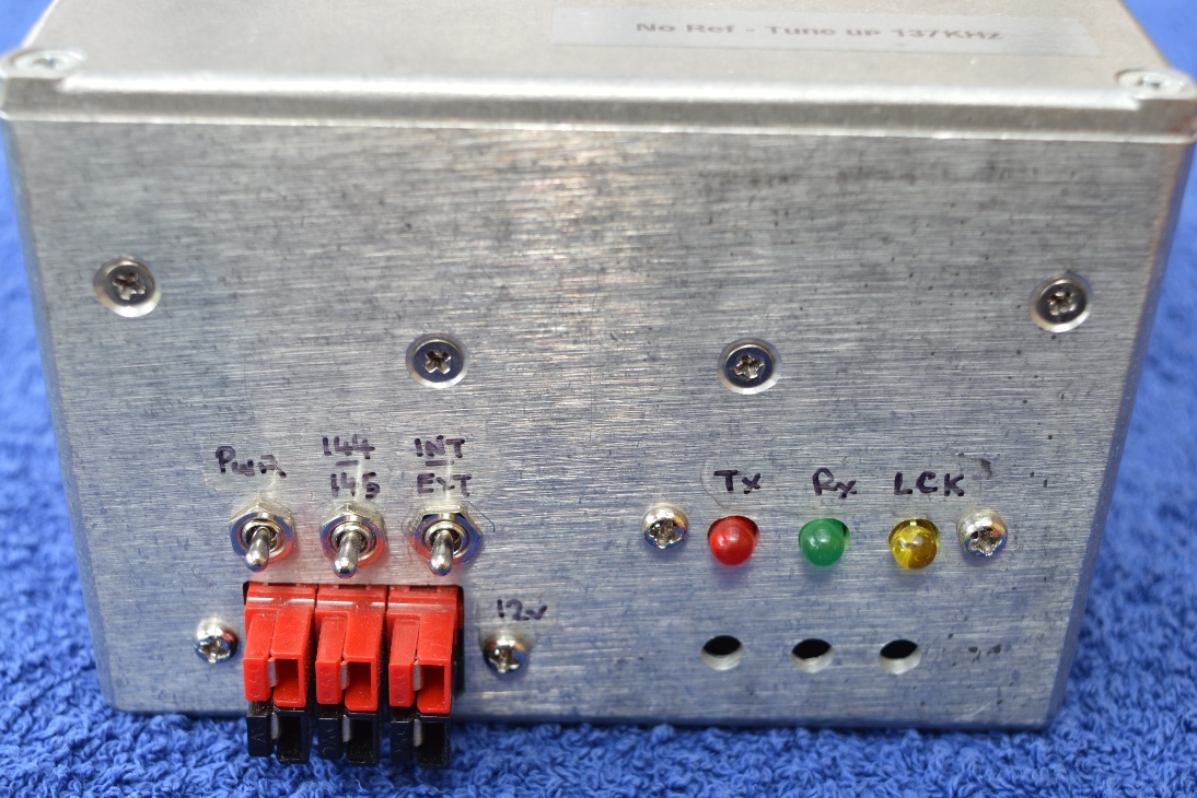
| 23 Sep 2019 | This is my 47GHz compact transverter. The transverter module is a Kuhne MKU 47 G2 (TX 46mW, RX 6db NF) and the LO is a modified Elcom synthesizer module. The antenna changeover relay and transverter control electronics were made by Rudi, OE5VRL and Hans, OE2JOM. The LO frequency can be changed by a switch on the front so the I.F. frequency is either 144MHz or 145MHz (for 47,088MHz). A small meter is connected to the monitor output of the transverter module to give an indication of TX power.
|
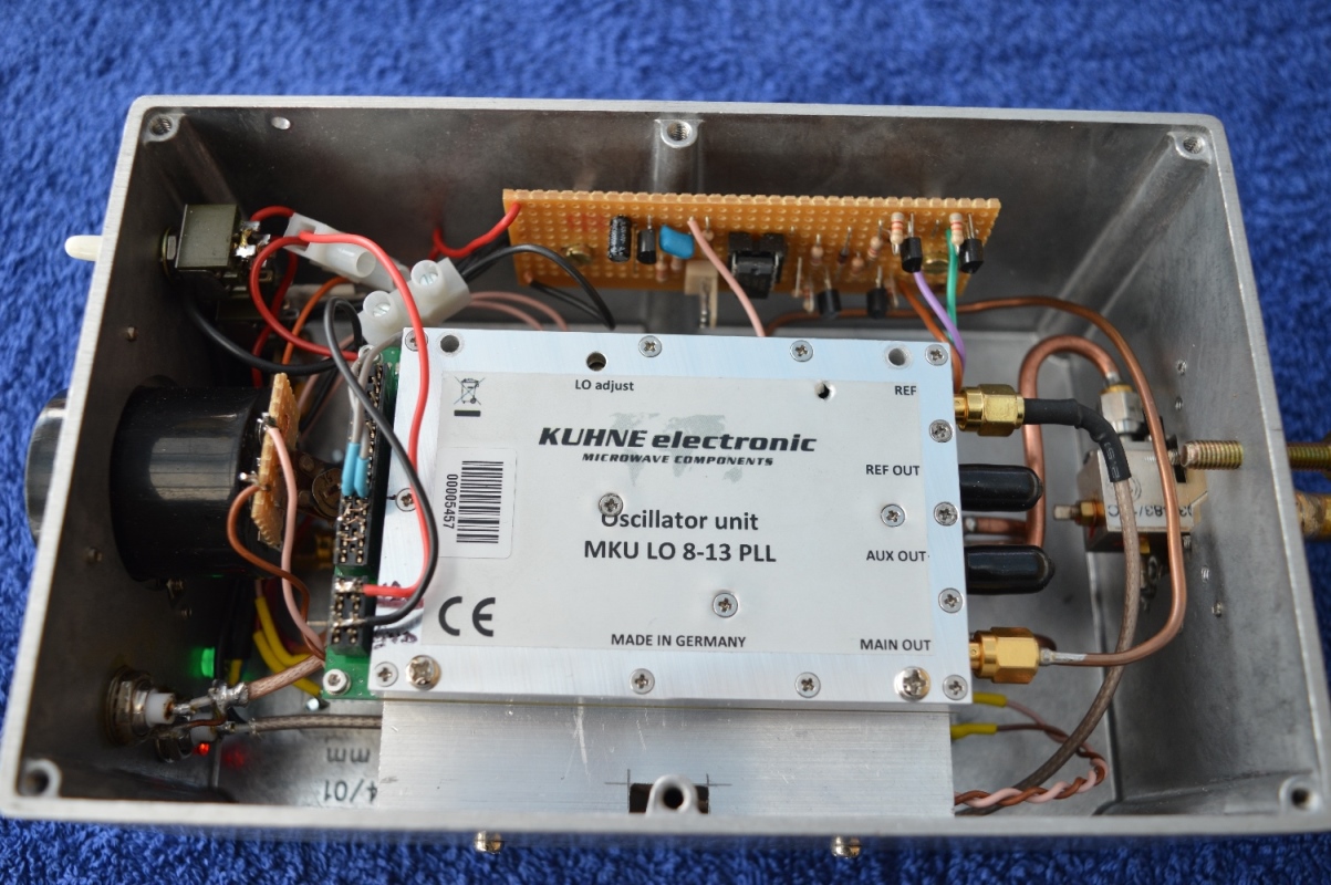
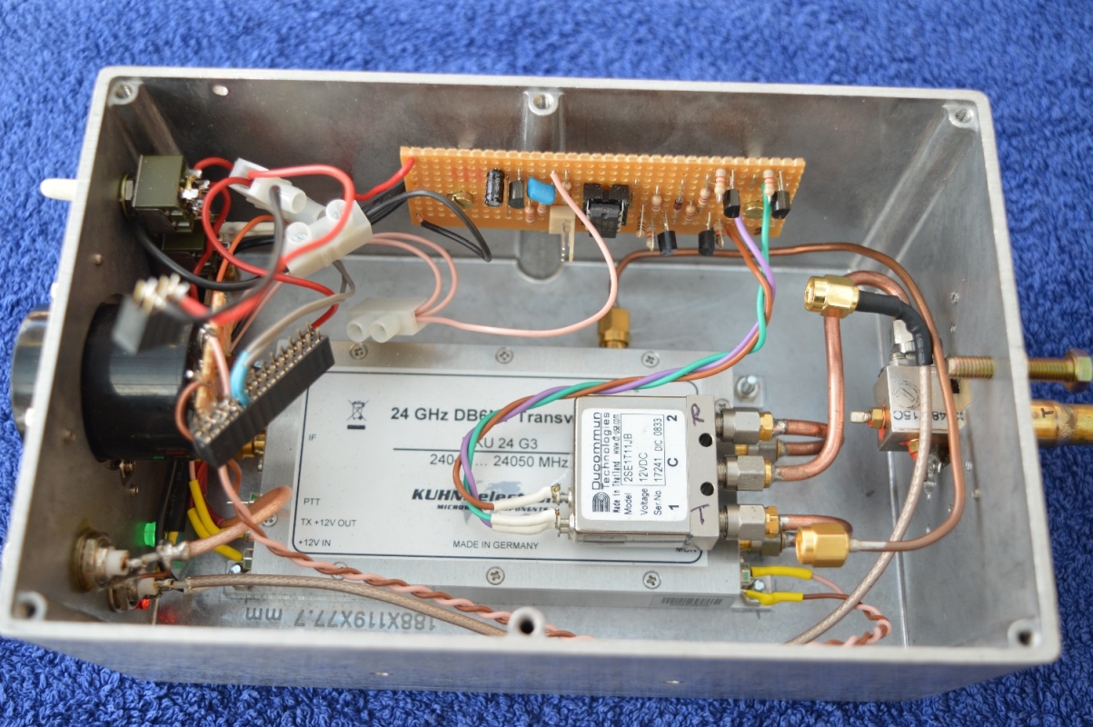
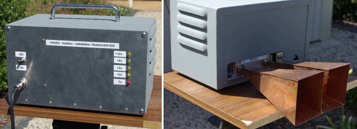
| 23 Sep 2019 | This is my 24GHz compact transverter. The transverter module is a Kuhne MKU 24 G3 (TX 2W, RX 3.5db NF) and the LO is a Kuhne MKU LO 8-13 PLL. The antenna changeover relay is a Ducommun device rated to 26GHz (12v coil). TX/RX switching is managed by a Picaxe microcontroller. The LO frequency can be changed by a switch on the front so the I.F. frequency is either 144MHz or 145MHz (for 24,048MHz). A small meter is connected to the monitor output of the transverter module to give an indication of TX power.
|
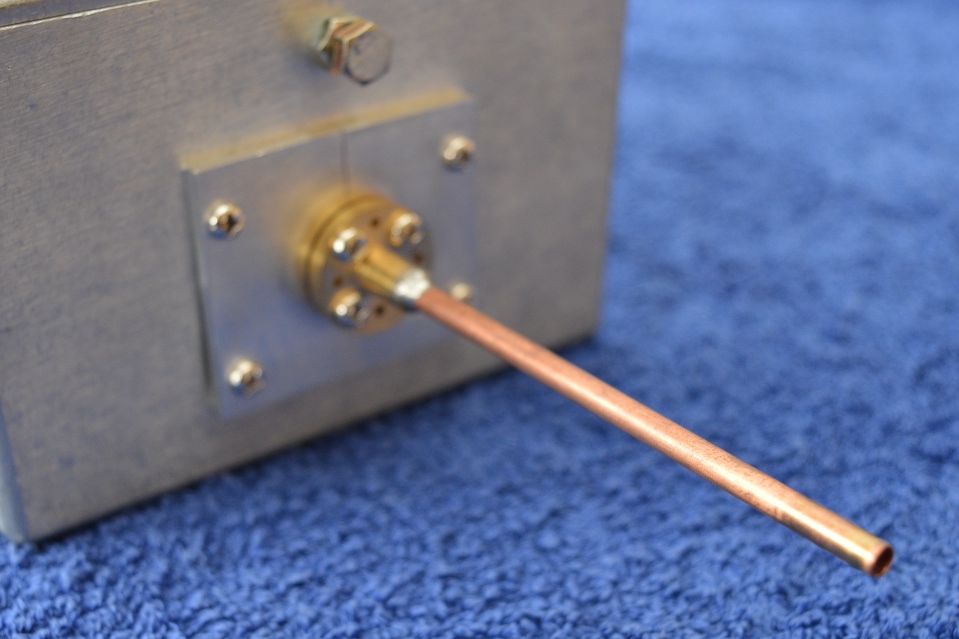
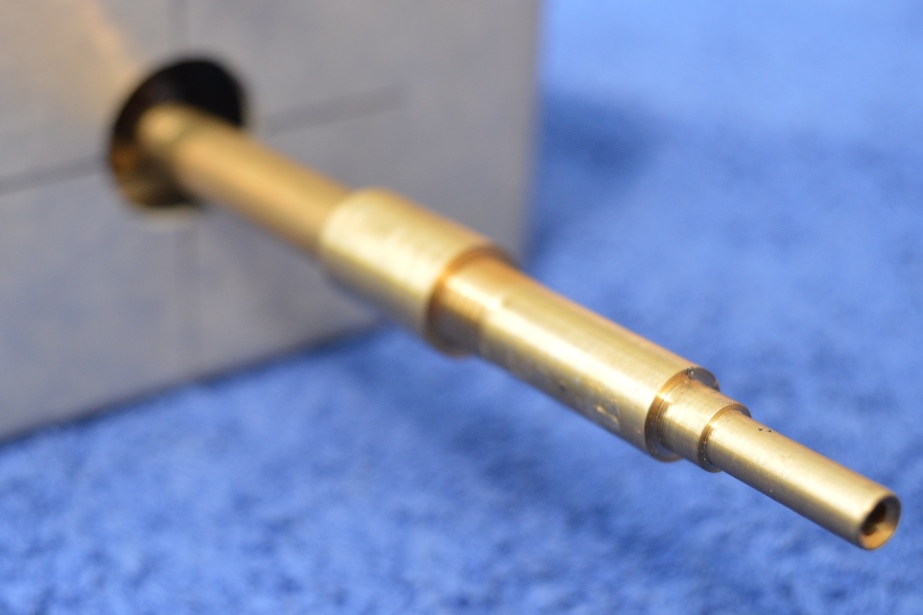
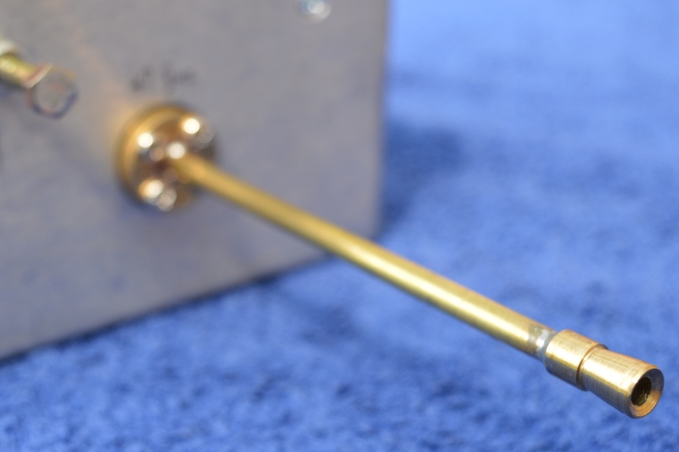
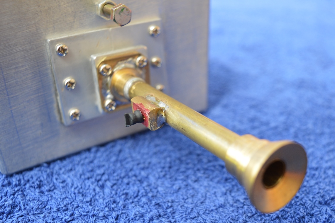
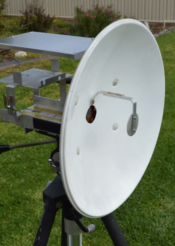
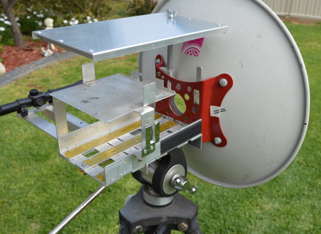
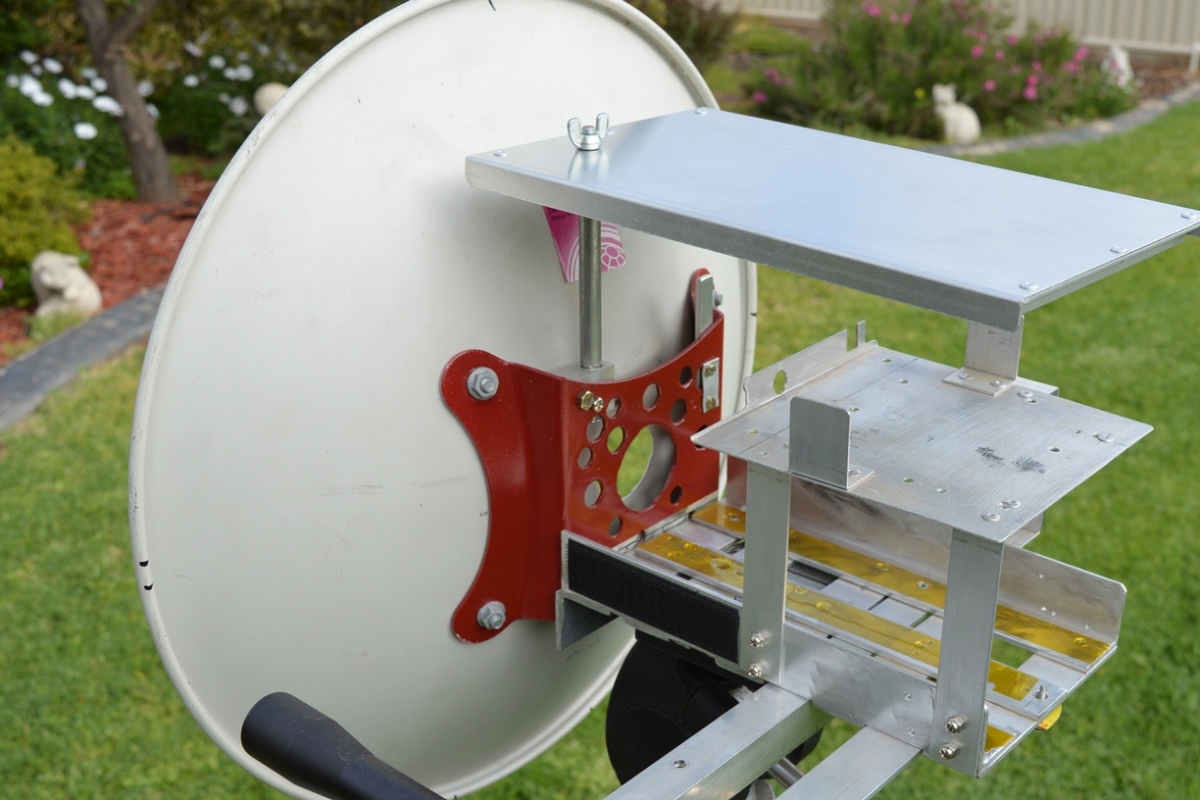
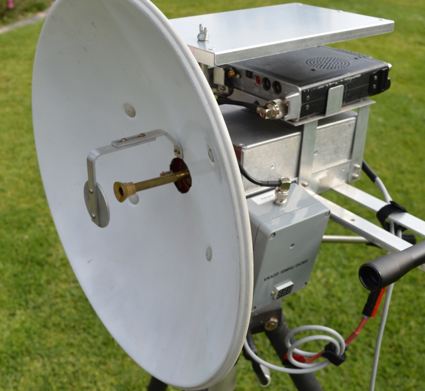
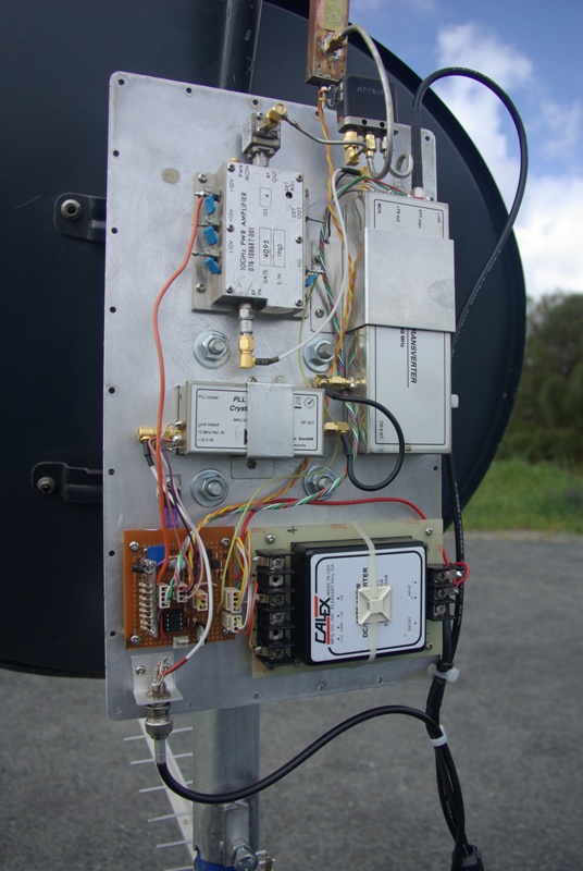
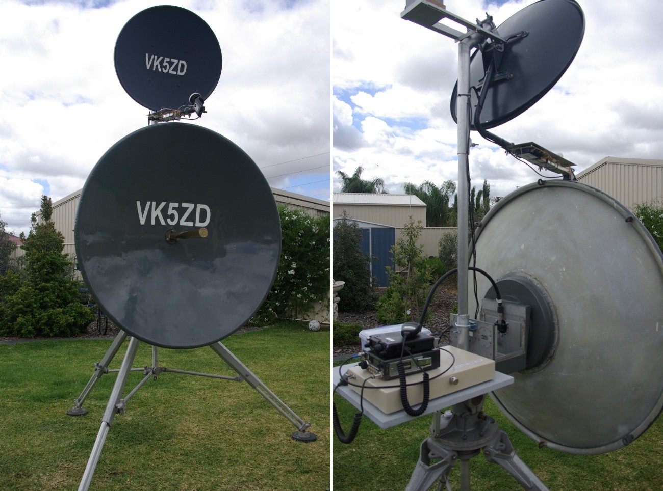
| 23 Sep 2019 | This is the antenna I use for my compact transverters. The dish is 40cm diameter and made from steel. It was salvaged from a 5GHz data link. I fitted a flat sub-reflector to the front. The transverter sits in a cradle behind the dish. An adjustment screw on the front of each transverter allows the feed to be positioned at the correct distance from the splash plate.
|
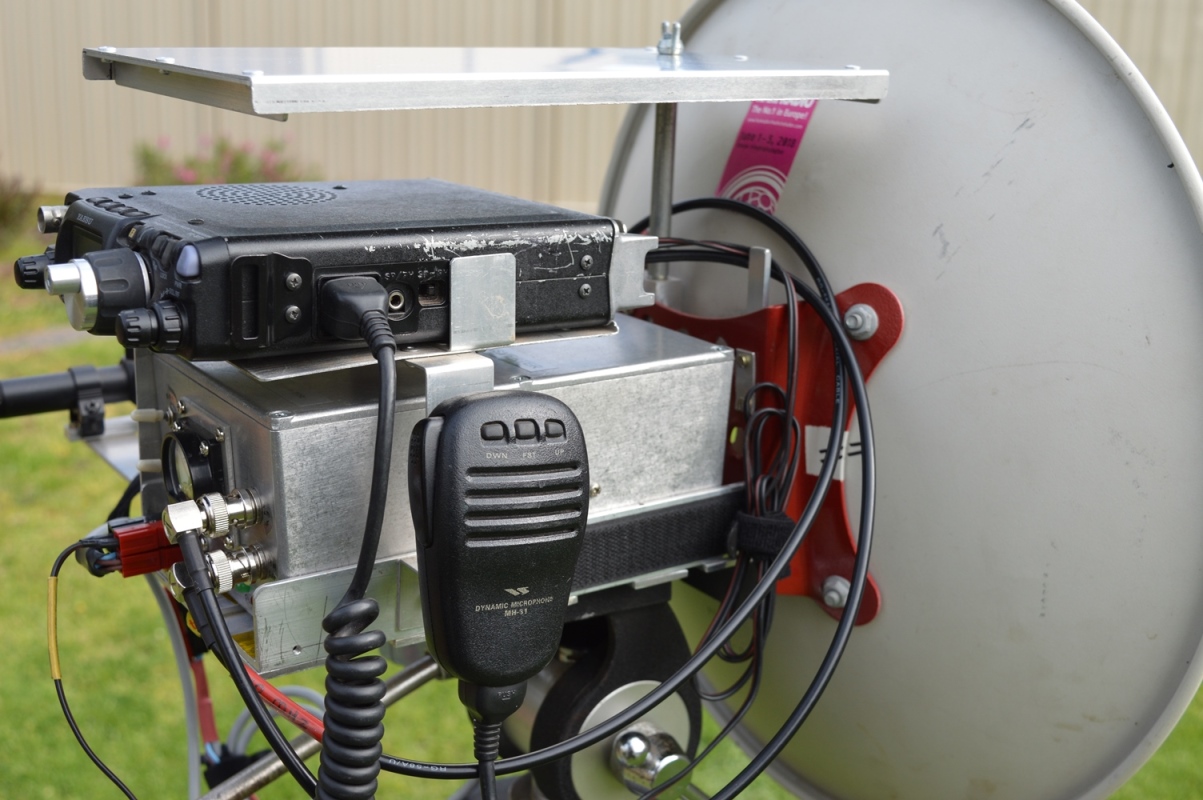
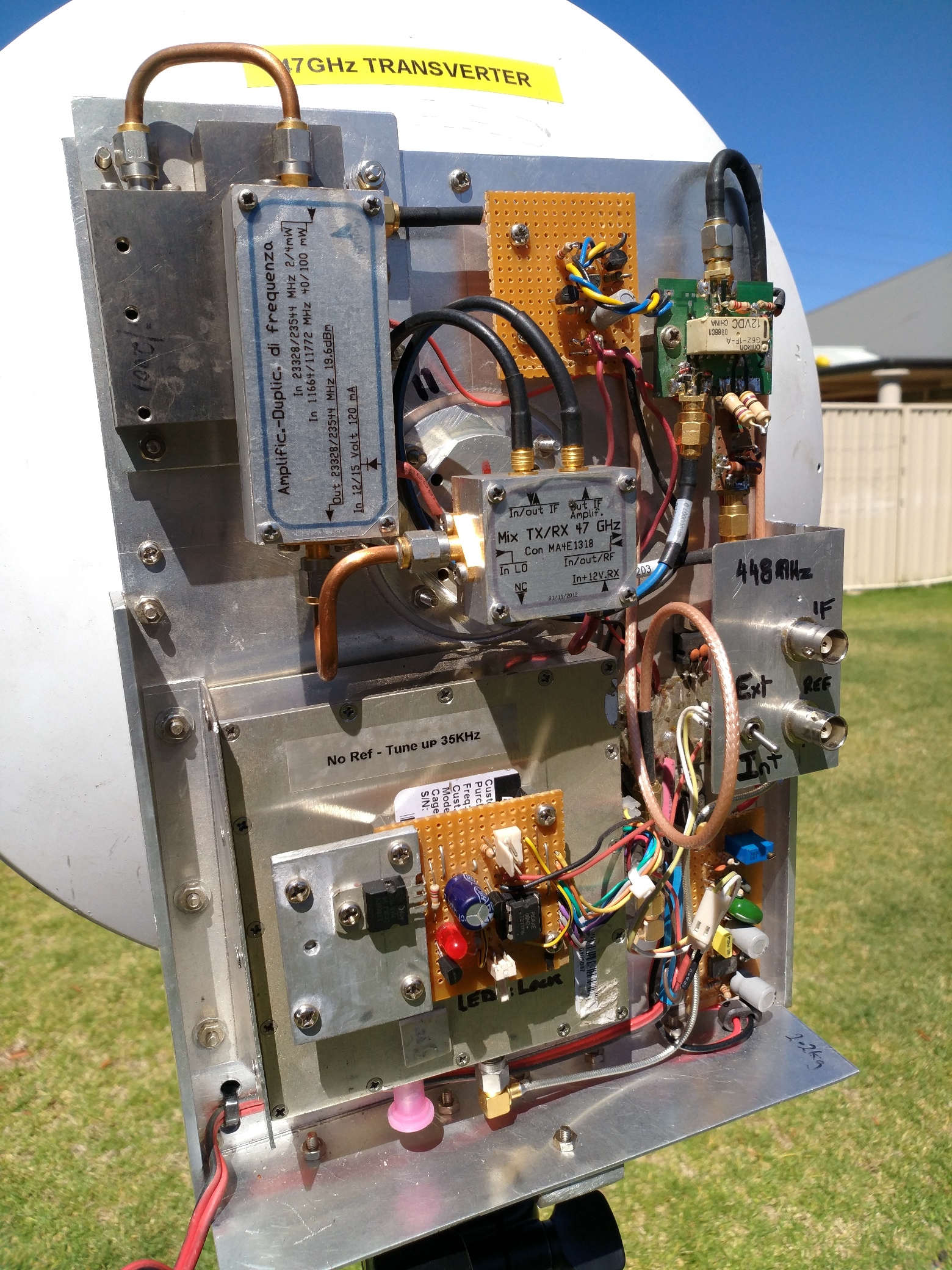
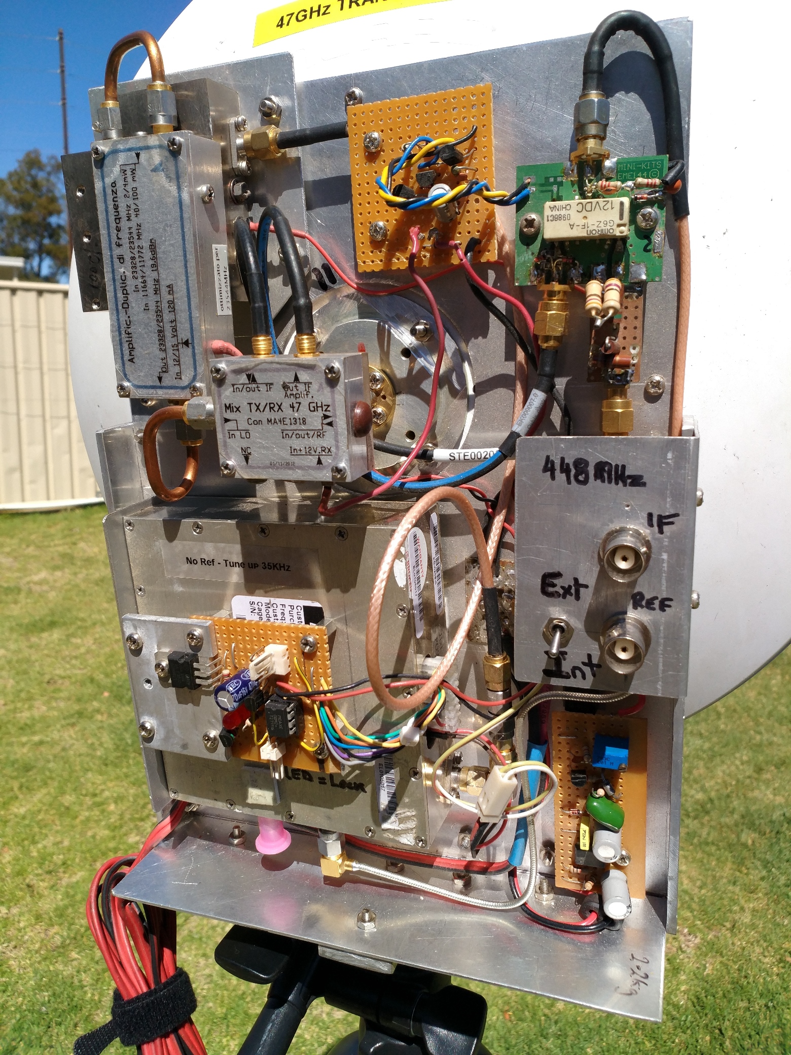
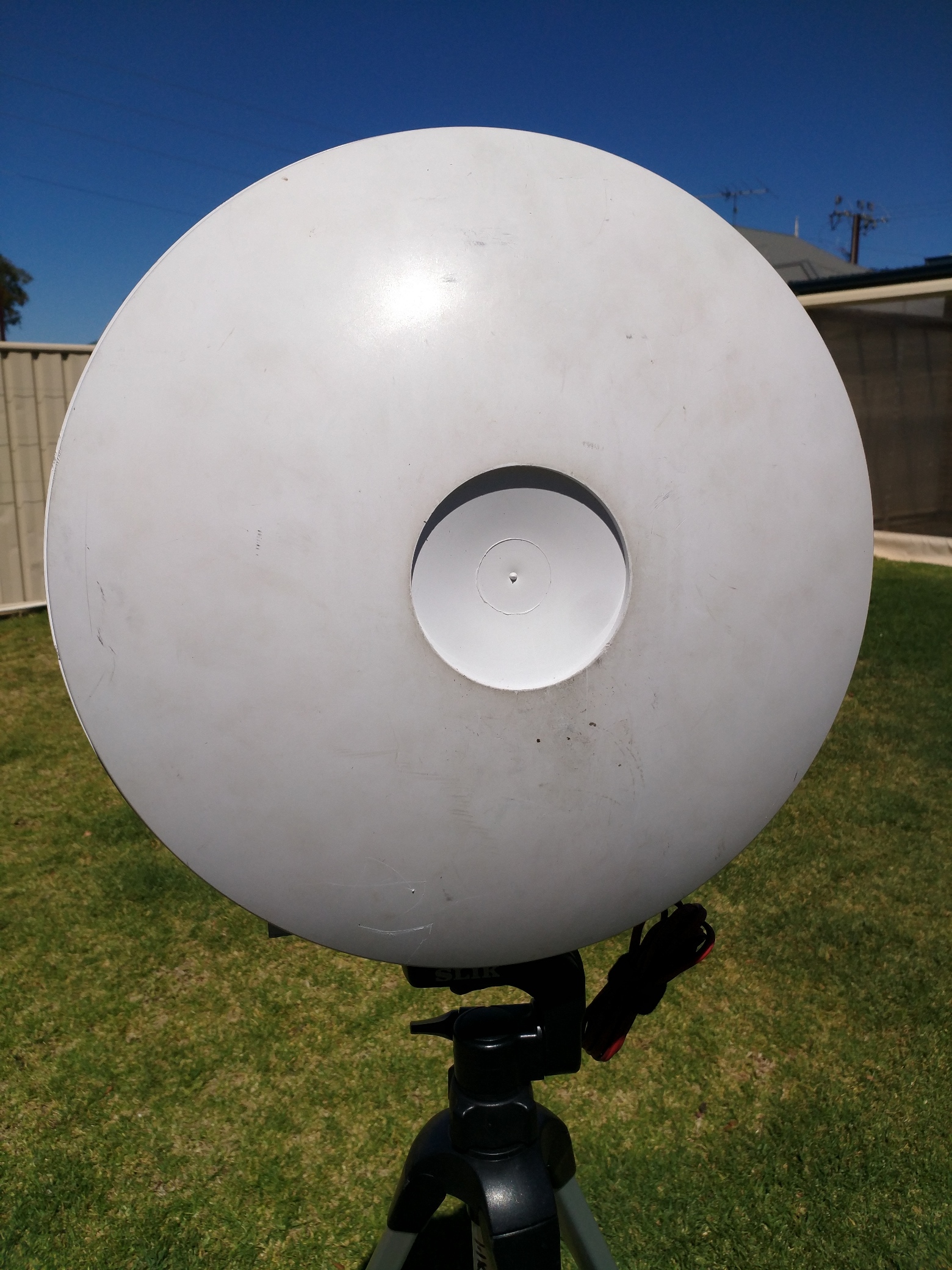
| 26 Oct 2018 | This was my first my first 47GHz transverter which I built just over 2 years ago. This is a very simple 'bare-mixer' system. i.e. there are no gain stages at 47GHz. The L.O. starts with a surplus Elcom synthesizer. This particular model has provision for using an external 10MHz reference input. The synthesizer is programmed by a Picaxe 08M2 microcontroller to produce 11,660MHz. The output from the Elcom goes to a doubler to give a signal on 23,320MHz. This then goes to an amplifier (made by Armando, I3OPW) to bring the level up to +20dbm (100mW) which feeds a harmonic mixer using a Macom MA4E1318 antiparallel diode pair (also made by I3OPW). This doubles the frequency to 46,640MHz and mixes it with the 448MHz I.F. to give an operating frequency of 47,088MHz. The antenna is a surplus Nurad cassegrain dish with horn feed. The original horn (which was made for 30GHz) was cut back to improve the sub-reflector illumination at 47GHz. The transmit output power is around 150-200uW (that's micro-watts) and the receive noise figure is over 13db. Despite that, I've used it to make contacts over 50km. Click here to watch a short video of the contact.
|
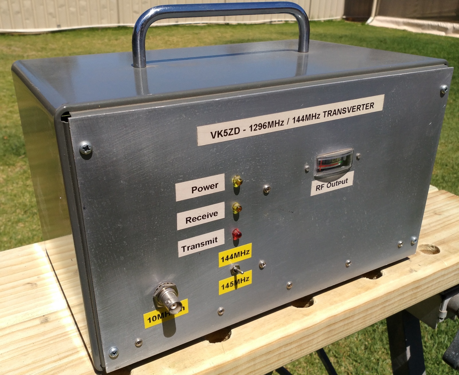
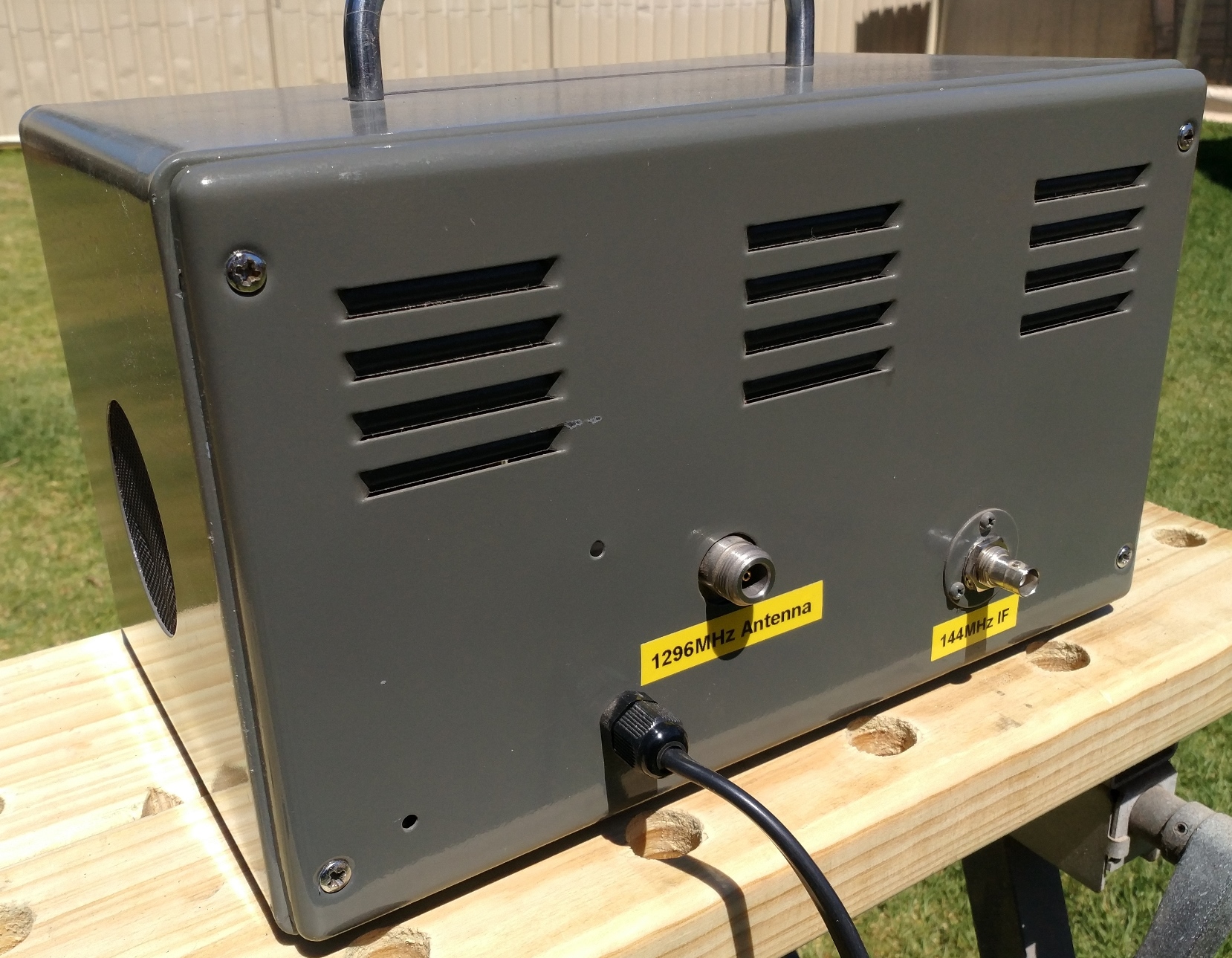
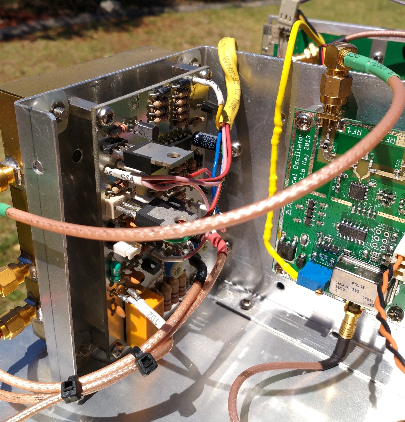
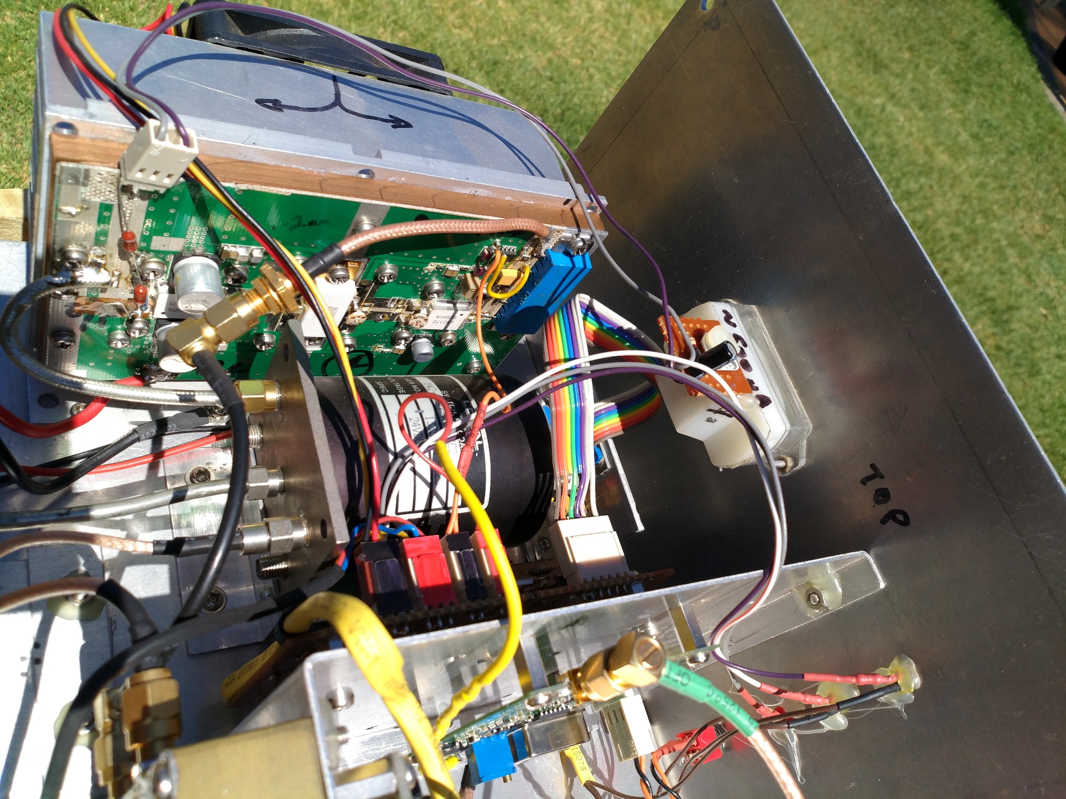
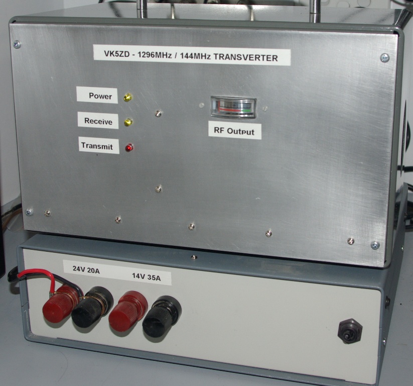
| 26 Oct 2018 | Update to the 8-Aug-2011 post about my first 1,296MHz transverter. Not long after completing that upgrade the power amplifier failed. A replacement FET was obtained which gives a bit less output (50w). I also replaced the crystal oscillator (96MHz multiplied up to 1,152MHz) with a synthesized ZLPLL board from ZL2BKC which is (a) far more stable and (b) allows me to lock it to an external 10MHz reference. I can also switch the I.F. to either 144MHz or 145MHz.
|
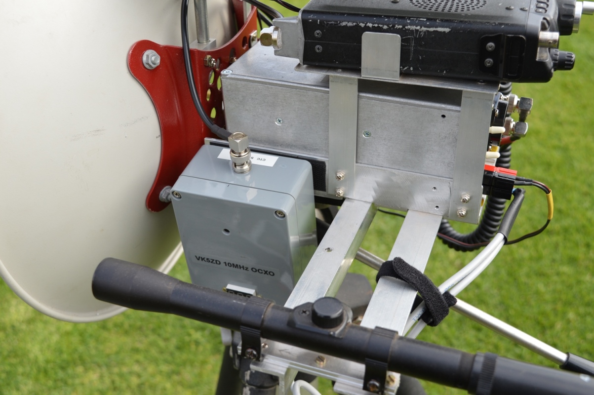
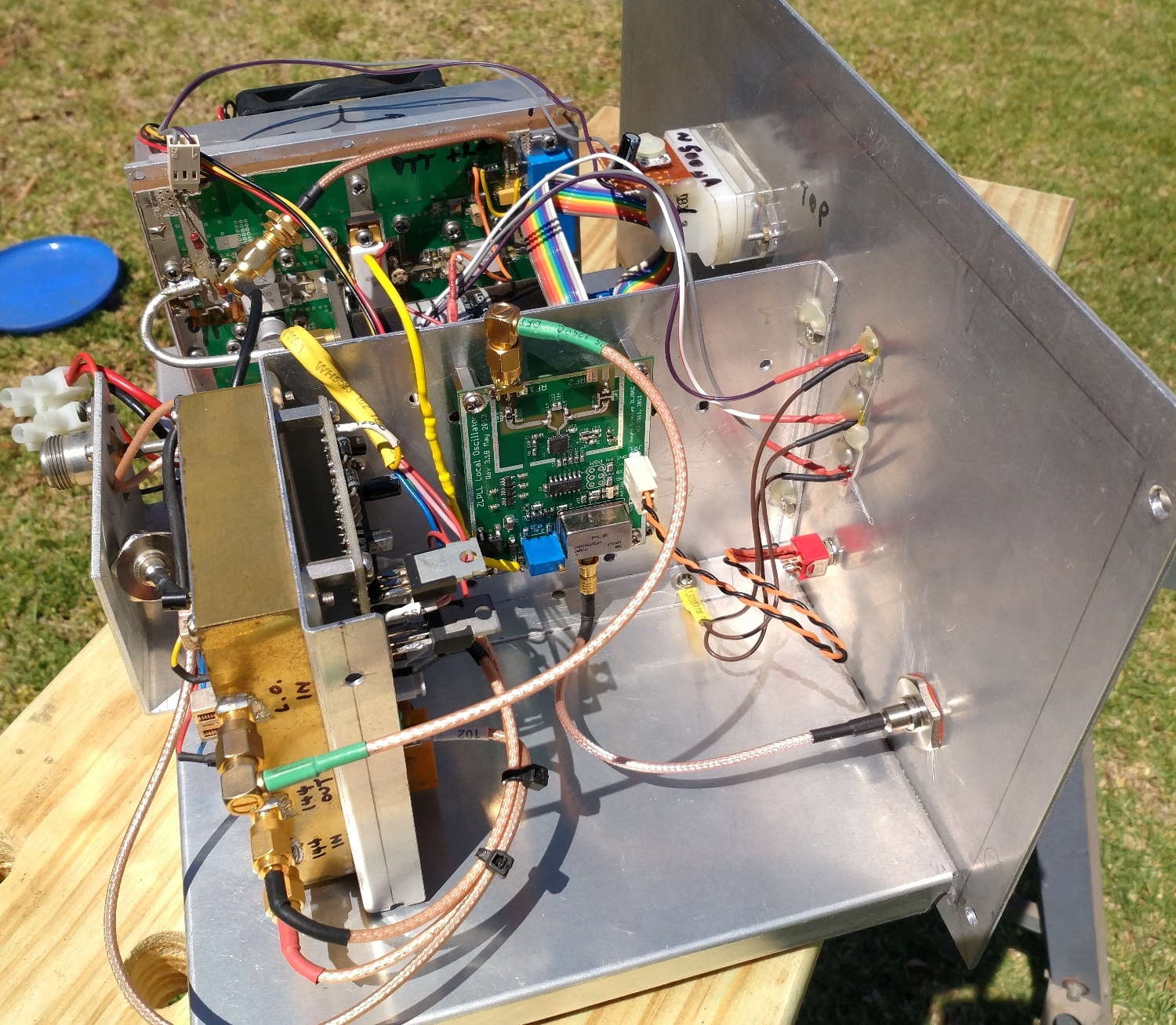
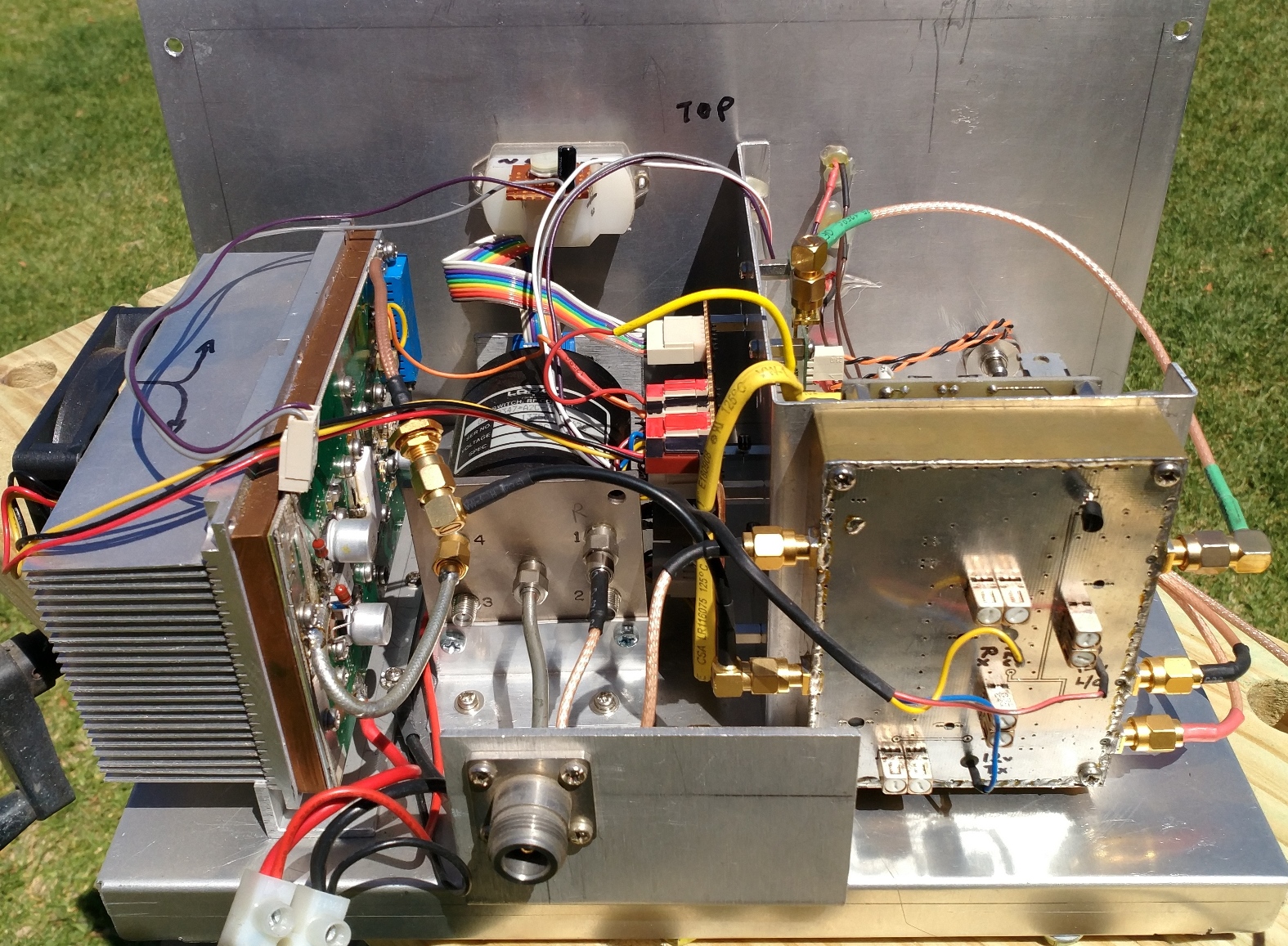
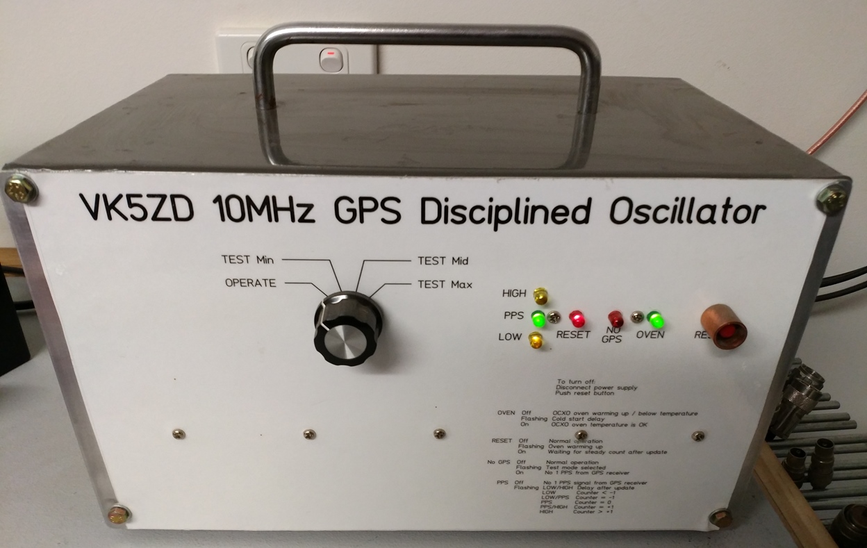
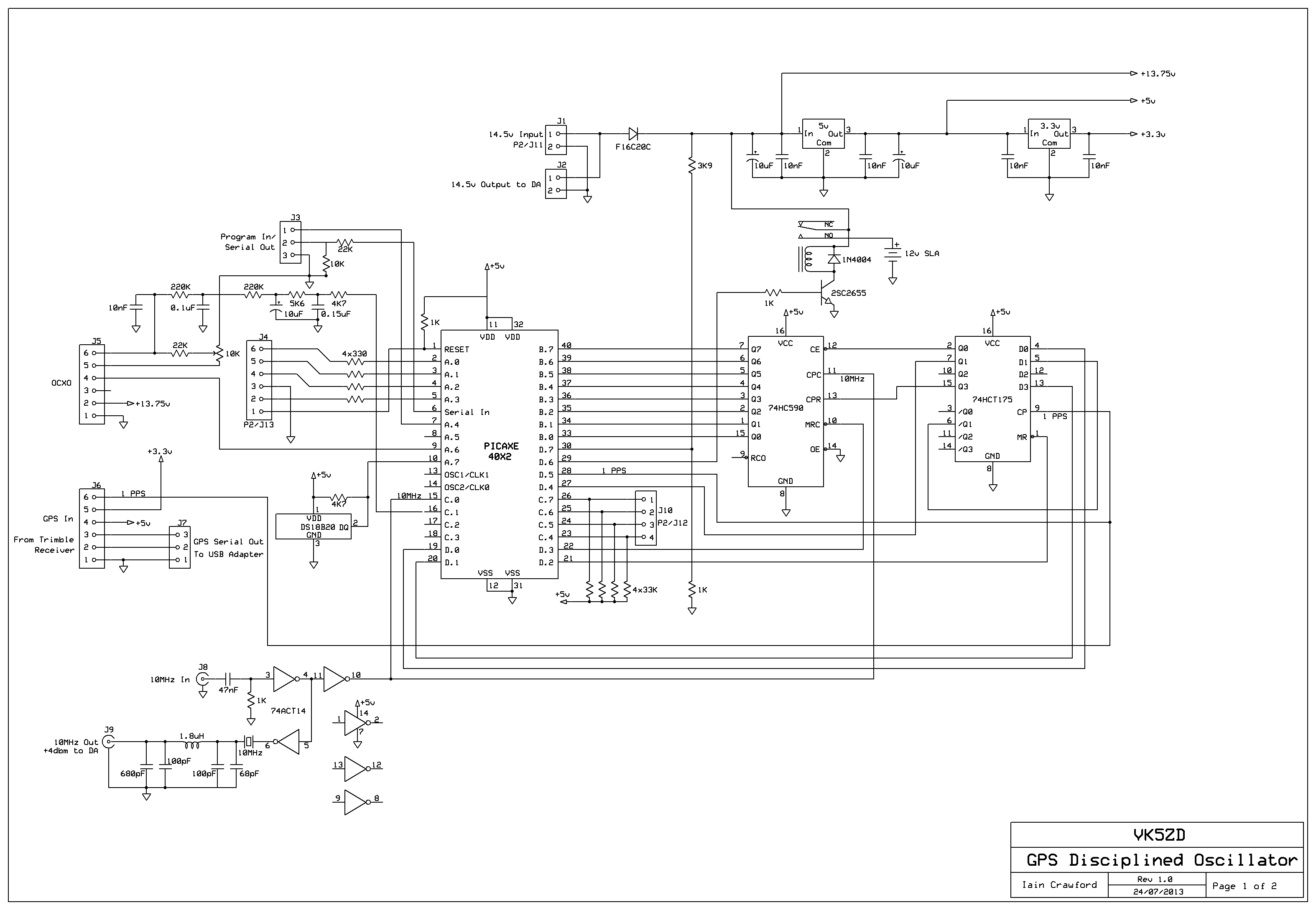
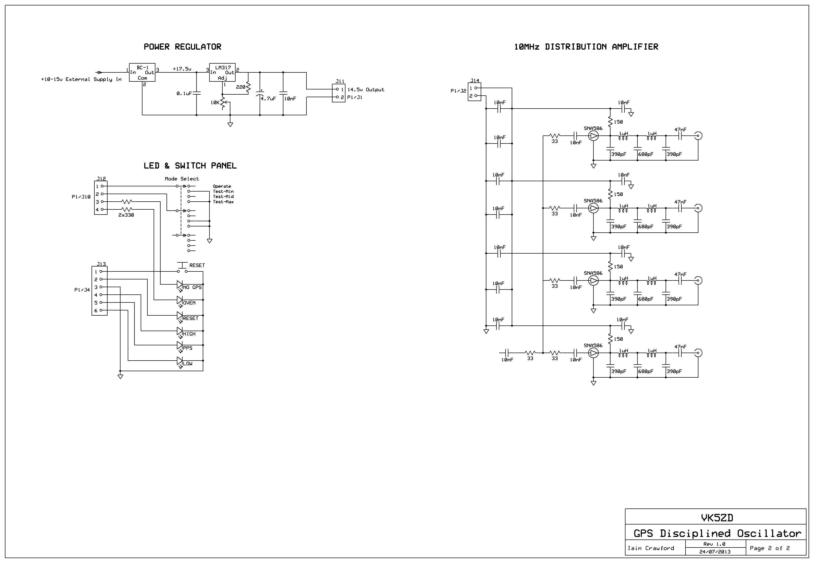
| 22 Oct 2018 | I wanted an accurate frequency reference but, when I went looking, most of the GPS derived references were quite expensive. Therefore, I decided to build my own which has been running for a few years now. This design uses an internal OCXO to generate a 10MHz signal. The 1pps output from a GPS receiver is used to gate a counter looking at the 10MHz signal. I only use an 8-bit counter. With 10Mhz going in, the count will alternate between 0x80 and 0x00 each second. I only look at the odd second count which should always be 0x80. Any error will cause the count to go high or low and from this I adjust the frequency control voltage for the OCXO. The amount of adjustment depends on how long it's been counting before I detect an error (greater time = smaller correction). Everything is controlled by a PICAXE microcontroller. Select this link to get the PICAXE code.
|
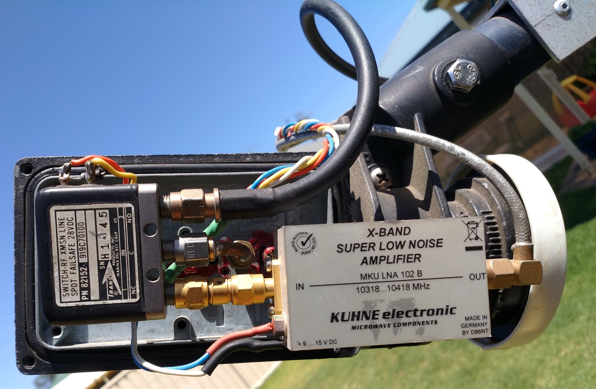
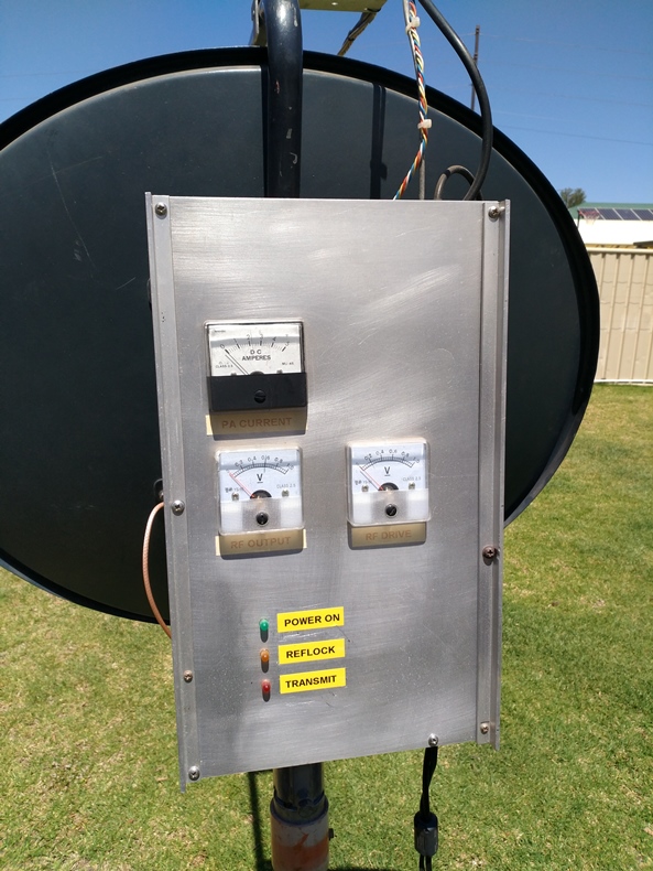
| 22 Oct 2018 | There has been an update to my DB6NT 10GHz transverter. I've added some metering so I can see that the transmitter is behaving itself. The waveguide feed is gone. The Tx signal now goes through a length of LMR-240 coax and the Tx/Rx changeover relay is at the feed point together with a LNA for the receiver.
|
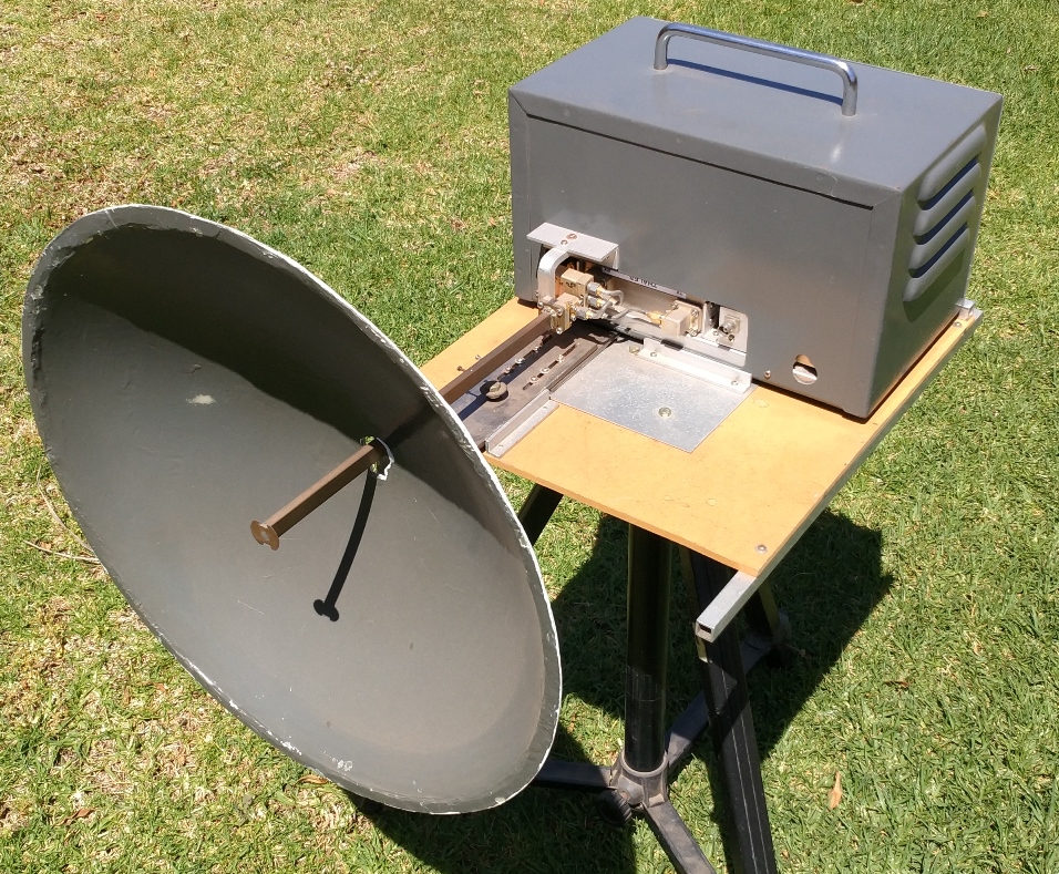
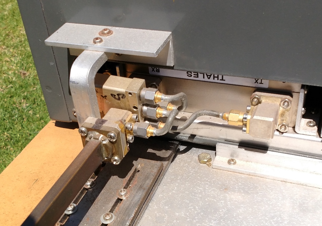
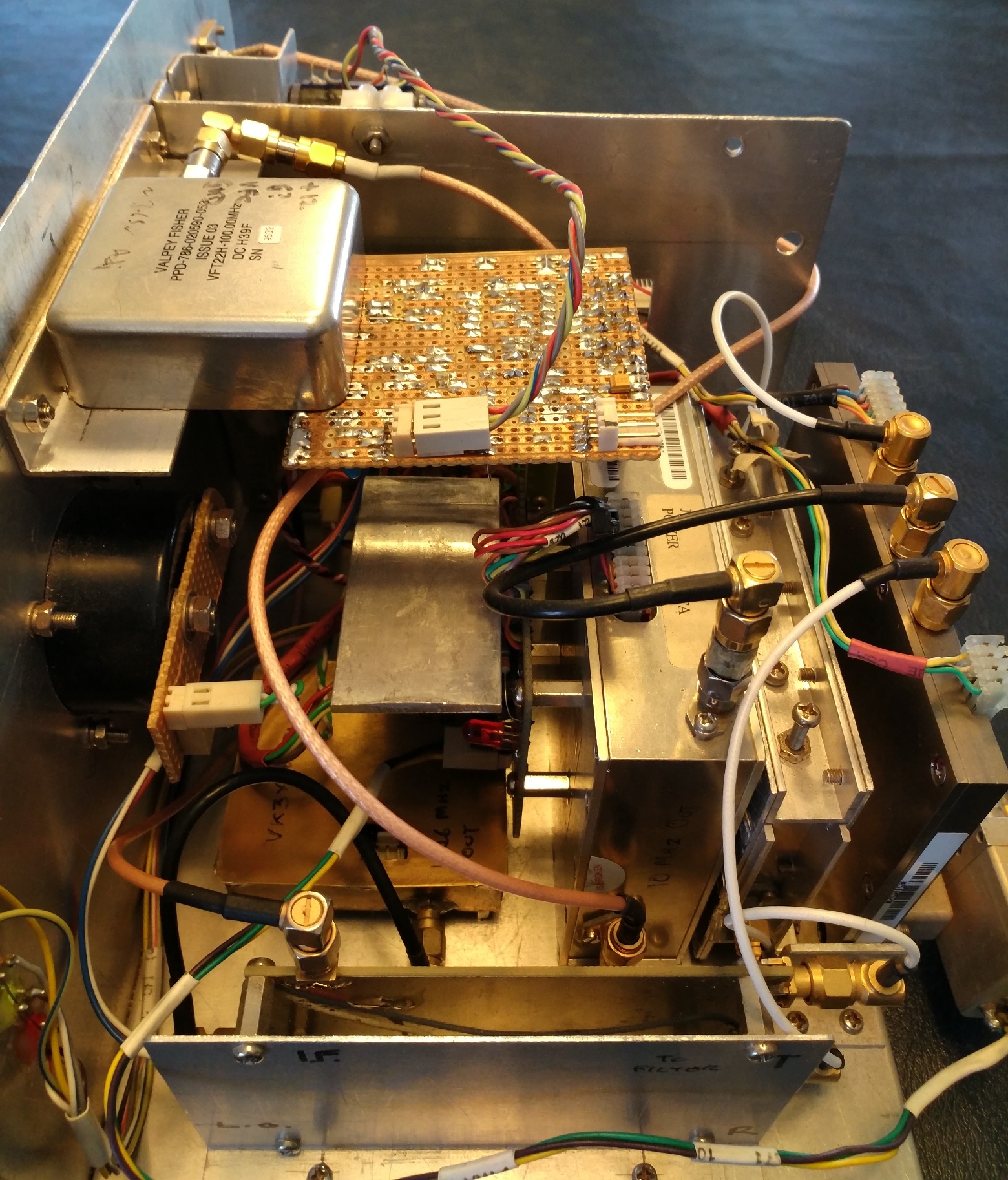
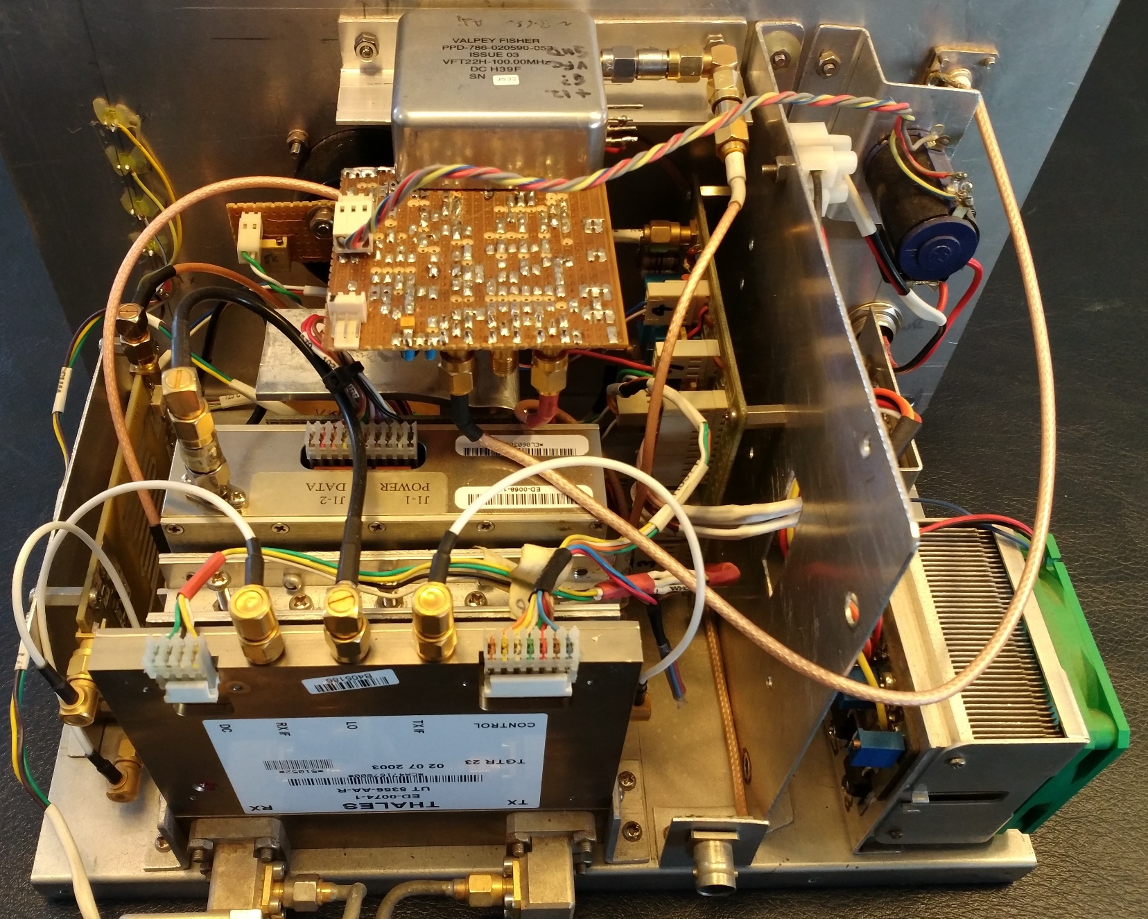
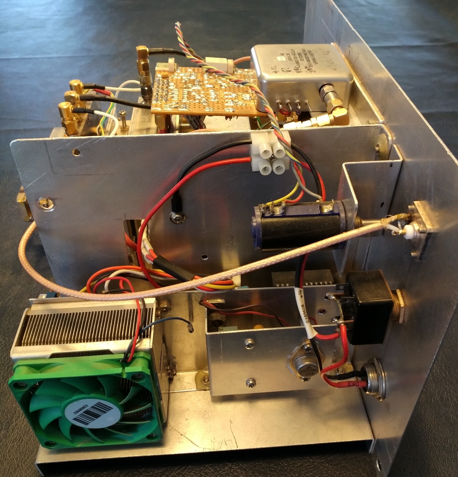
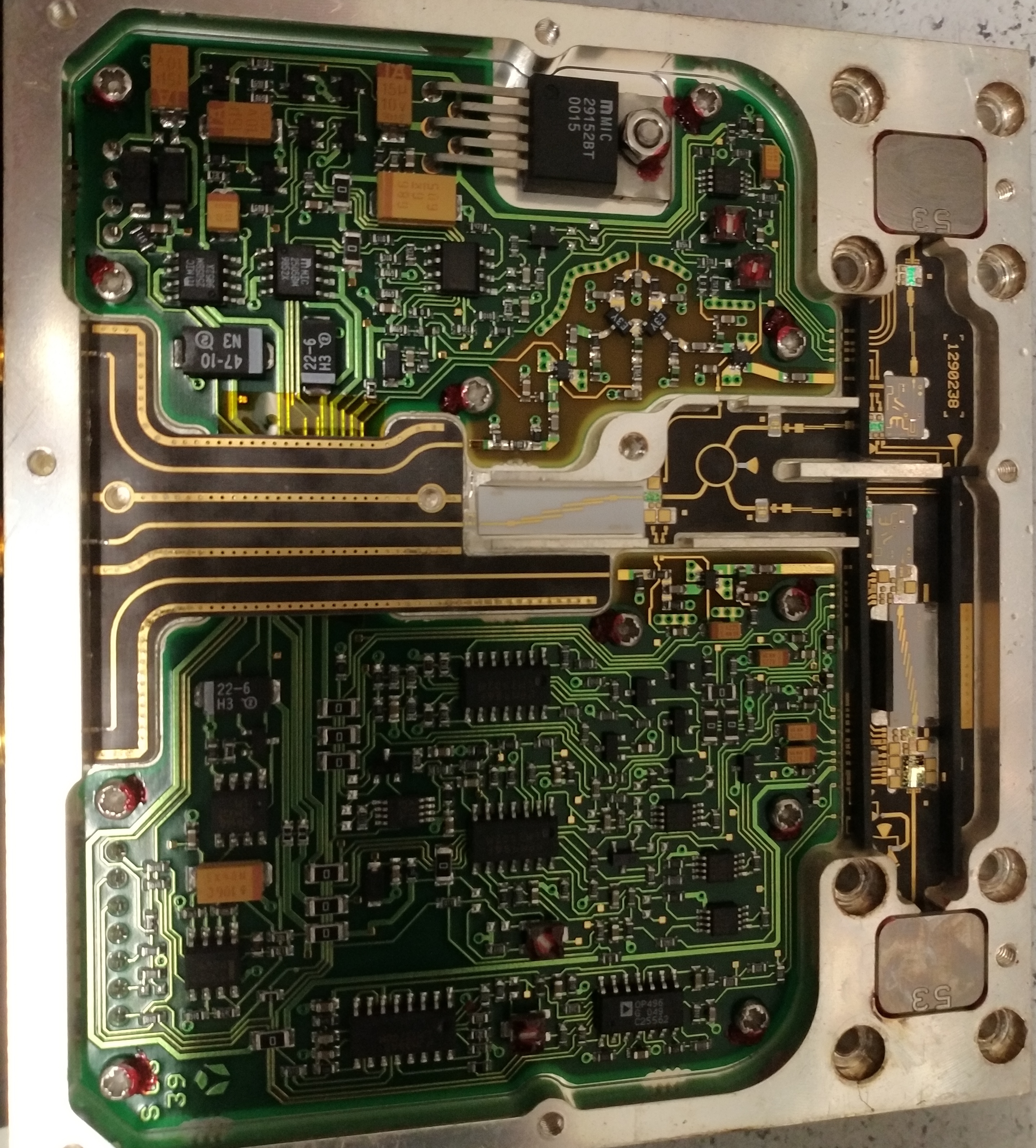
| 22 Oct 2018 | Update to my original 24GHz transverter. It now has a 40cm dish (also home brew). The Tx/Rx switching uses a SMA relay with WR42 transitions to connect it to the Thales module and the waveguide to the antenna. There is a 'penny feed' on the end of the waveguide. I've also added a meter to indicate output power (there's a directional coupler in the Thales module). The last image shows the interior of the Thales module.
|
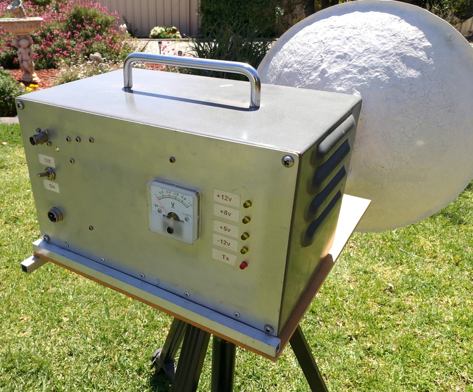
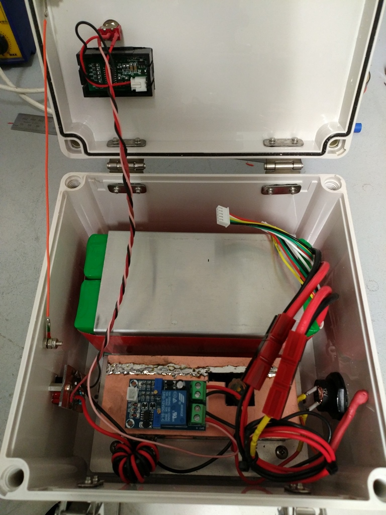
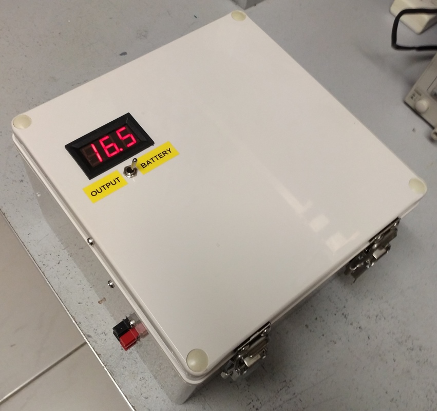
| 22 Oct 2018 | A portable power supply is always a useful item. This contains 2 x 10AH 4 cell LiPo batteries in parallel. There is an automatic low voltage cutoff set to 13.2v (3.3v per cell) to stop me destroying the batteries by running them too low. A buck converter in a shielded box (to reduce noise) reduces the output voltage to 12.2v. The digital voltmeter can be switch to show either the battery or output voltage. I use this to power my microwave transverters and radios when operating portable.
|
| 11 Nov 2011 | I've completed my 24GHz transverter which is based on a 23GHz Thales unit purchased on eBay. Preliminary test indicate that it's working, but I'll be conducting a long range test this coming Sunday. I don't have a suitable antenna switching device so I just built two antennas (25db gain horns).
|
| 16 Oct 2011 | My DB6NT 10GHz transverter has been updated with the addition of a 3W PA that I've had lying around for a couple of years. Thought it's about time I made use of it. The electronics have also been moved to the rear of the dish and I'm using WR75 waveguide up to the feed.
|
| 08 Aug 2011 | I've done a re-build of my first 1296MHz transverter and added an 80W PA stage. This also required a new power supply (the PA needs 24v at 8A) which is in the box below the transverter.
|
| 19 Jun 2011 | I've just completed a weekend of contesting in the WIA winter VHF/UHF field day. Saturday was cold and wet and I spent almost as much time waiting for rain to pass as I did operating.
|
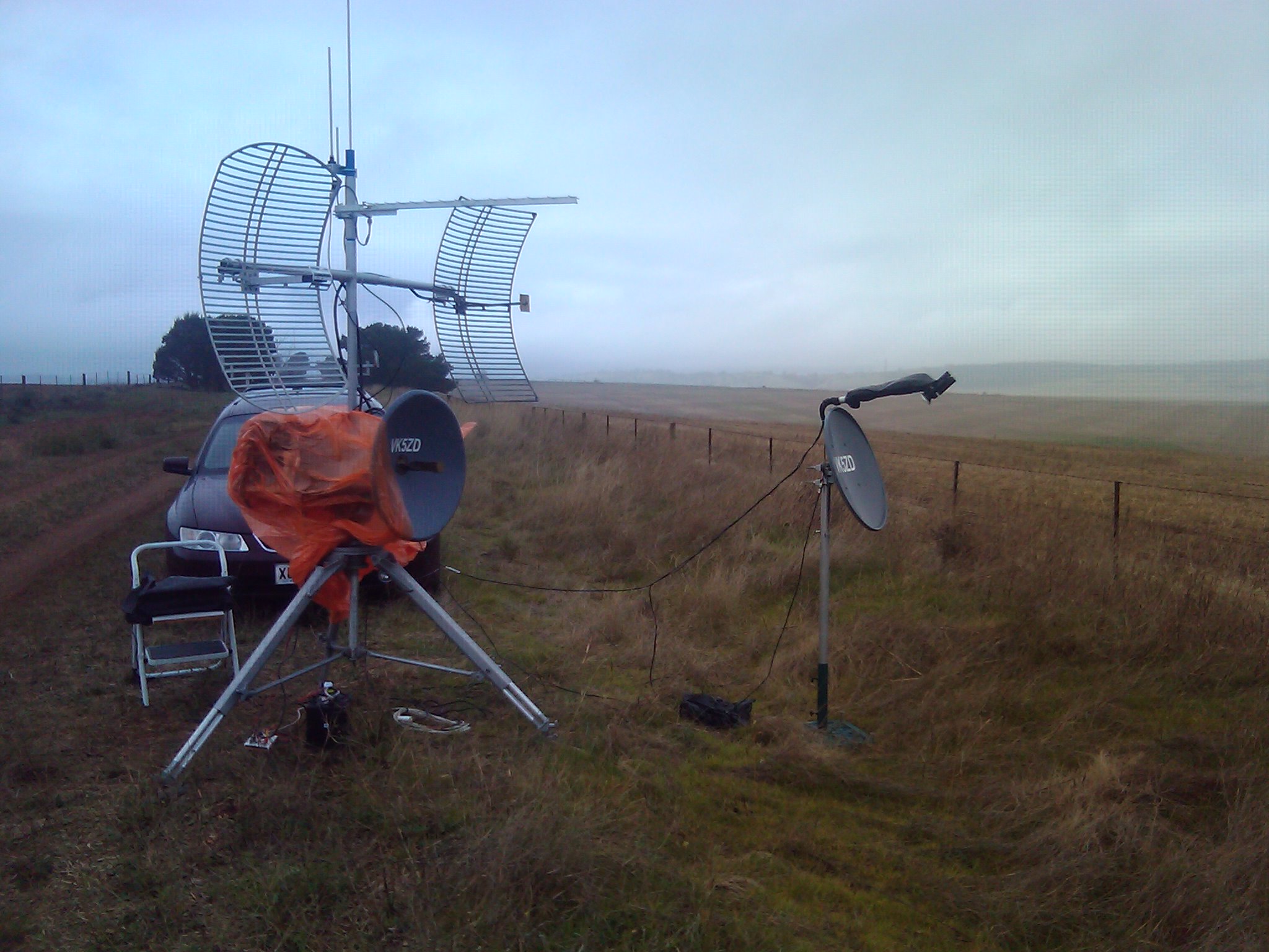
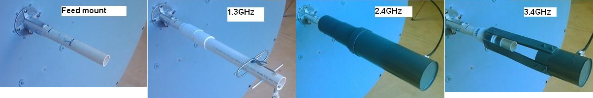
| 07 Jun 2011 | I recently aquired a 900mm dish prime focus courtesy of Darryl, Vk5HZ. The dish came with a feed for 5.7GHz which, according to the label, was originally designed for use in a grid antenna. Since I already have two dishes for 5.7GHz (60cm and 1.2m) I decided to use this dish for 1.3GHz, 2.4Ghz and 3.4GHz (the 5.7GHz feed was fitted to a spare grid antenna I had and it works well with ~28dbi gain). For 1.3GHz I made a 3 element yagi feed while for 2.4GHz and 3.4GHz I used a traditional 'coffee can' feed (actually licorice allsorts and chocolate coated nuts cans). A length a 20mm PVC water pipe was fitted to the feed point and the antennas were fitted to PVC joining sleeves that can slide over this pipe.
|
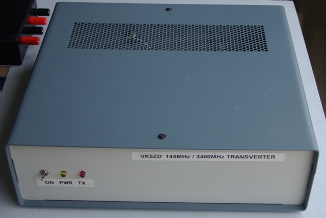
| 21 May 2011 | Added a PA stage to one of my 3.4GHz transverters. The output level is now 4 watts (previously ~40mW).
|
| 30 Apr 2011 | Rx fault in my VK3XDK 10GHz transverter has been found and fixed. Conducted some more tests and everything works fine. The receiver seems quite sensitive now.
|
| 23 Apr 2011 | First test of my VK3ZDK 10GHz transverter. Tx works fine but the receiver is seriously deaf!
|
| 19 Mar 2011 | Took part in my local radio club's effort for the John Moyle Field Day. The main effort was on HF but I also took the microwave gear to provide some contacts for other local stations.
|
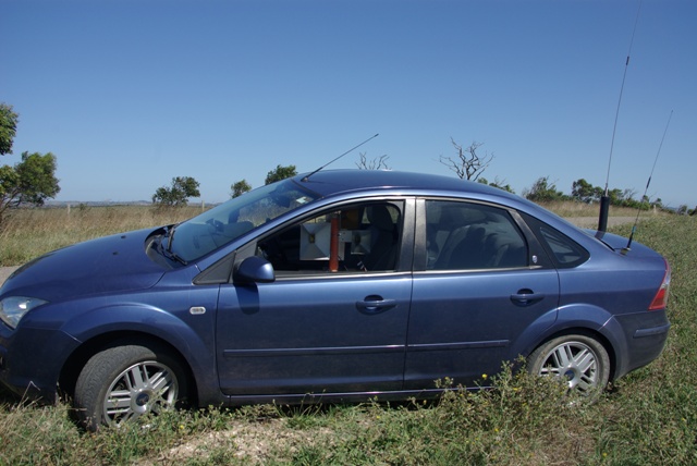
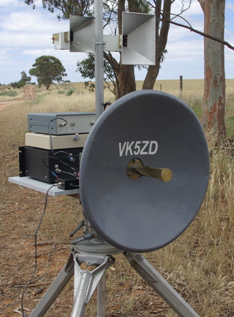
| 14 Mar 2011 | Succeeded in setting two new VK microwave records today for mobile contacts. 144.9km on 5.7GHz and 165.4km on 10GHz. In the picture the 5.7GHz horn is on the right and the 10GHz one is at the top. The larger horn on the left is for 3.4GHz. I need to try a bit harder to beat the current mobile record (170.1km) on that band.
|
| 17 Jan 2011 | Went to Yorke Peninsula for the summer VHF/UHF field day. Tried my 1.2m dish for the first time on 5.7GHz. Made contacts on all bands up to 10GHz.
|
| 10 Dec 2010 | Did some short range (about 30km) tests on 3.4GHz and 5.7GHz with Keith, VK5OQ. I had two transverters for each band. Everything worked as expected, including the fact that one of my 5.7GHz transverters is still deaf. I recently did some 'snowflaking' on the LO multiplier which significantly increased the LO drive to the mixers. This increased the audible mixer noise in the I.F. transceiver but did nothing to improve the sensitivity. I now suspect the MMIC in the first RF stage has died.
|
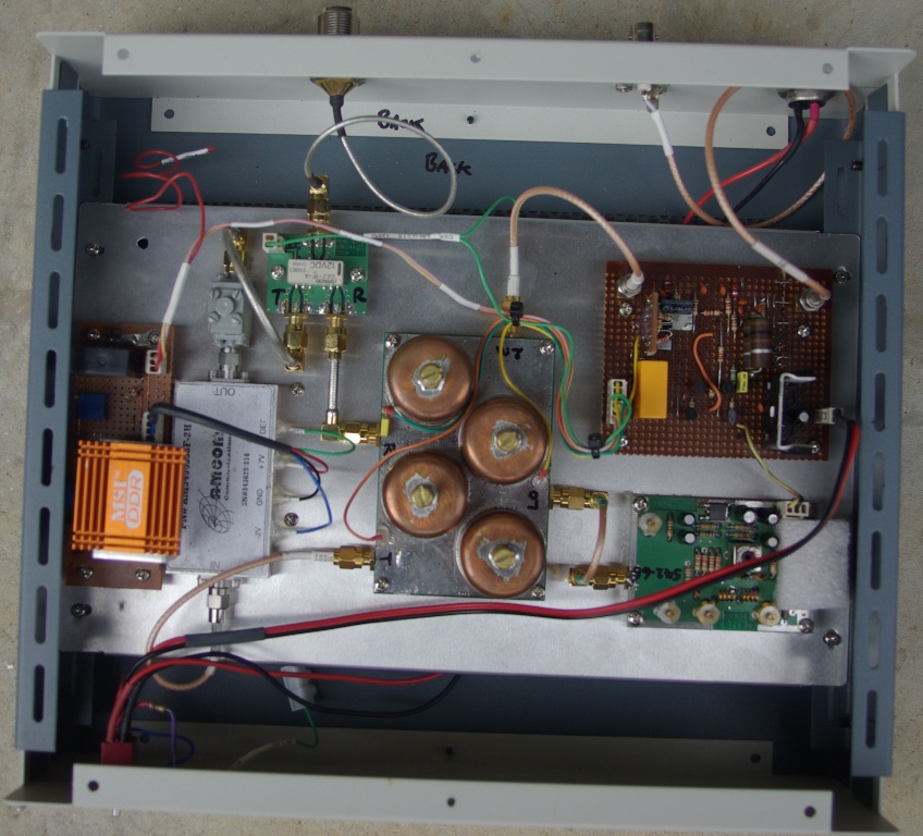
| 25 Nov 2010 | Almost two years ago I bought a surplus 'ioLink 1' RF unit. This is part of a system that provides a full duplex wireless data link. The device is designed to operate on one a three fixed frequency pairs around 5.8GHz. The original unit has three external coaxial connectors; (1) transmit IF input & DC power, (2) receive IF output and RSSI and (3) 5.8GHz antenna. The transmit and receive frequencies are 60MHz apart and the device includes a diplexer for full duplex operation. The transmit IF frequency 110Mhz which is mixed with the LO signal to produce the transmit output frequency. The same LO signal is mixed with the receive input frequency to produce an IF of 170MHz. This is then mixed with a second LO on 240MHz to produce a second IF of 70MHz. Separate VCOs are used to generate the LO signals each with its own PLL referenced to a common 10MHz TCXO. This picture shows the PCB before modifications.
The ioLink unit has now been modified to be a 5.7GHz transverter. A Picaxe was added to program the PLL for the required LO frequency and handle the T/R switching. The receiver side is left running all the time but a relay was added to switch the power to the PA device. The diplexer was removed and replaced with an antenna changeover relay. On the receive side, the 170MHz and 70MHz filters, the second mixer, the second LO and three of the MMICs from the IF stages were removed and replaced with a simple 144MHz filter. The net result is a 5.7GHz transverter with about +29dbm transmiter output for an outlay of under $100. This picture shows the modified PCB.
|
| 25 Nov 2010 | Here is a picture of 3.4GHz transverter #2. It still need a PA as the transmit output power is only about 20mW.
|
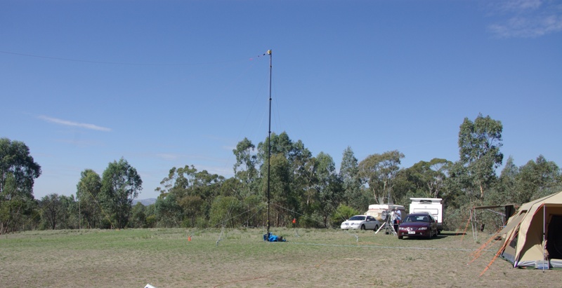
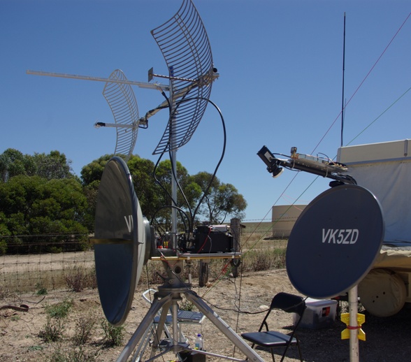
| 23 Nov 2010 | As mentioned previously, I recently aquired a 1.2m dish and tripod. Since then I've added an equipment platform and a short mast to hold the 10GHz offset dish. I now need to add a sighting system so that it can be accurately pointed to a given bearing. In time I also intend to make feeds for 1.2GHz, 2.4GHz and 3.4GHz (not 10GHz because it will probably be too hard to aim).
|
| 23 Nov 2010 | A few things have happened since the last posting so here's a summary (in no particular order). 3.4GHz transverter #2 has been mounted in a box (but still needs a PA). 3.4GHz transverter #3 has been sold to a local ham. I did some checking on my 4-in-1 transverter and found that there was quite a lot of spurious output on 2.4GHz so I fitted a filter to clean this up. I also discovered that the receive half of the 5.7GHz transverter is quite deaf. I have completed the conversion of a commercial 'ioWave' unit to a 5.7GHz transverter and it seems to work quite well. I made a couple of 10GHz contacts with Rex (VK7MO) during his travels through SA. I have aquired a 1.2m dish with tripod and 5.7GHz feed; a very robust (and heavy) item. More updates (and pictures) soon.
|
| 14 May 2010 | I've been doing some more experiments with WBFM on 10GHz. The traditional method for doing this is to use a Gunn oscillator/detector. While these work OK, they suffer from some of disadvantages:
(1) Poor frequency stability.
(2) Poor receiver sensitivity.
(3) The other station must transmit on a different frequency (difference being the chosen I.F.).
I then tried a 'motion detector' module that used a DRO. This was much more stable than the Gunn oscillator but difficult to modulate since it's almost immune to variations in the supply voltage. I finally settled on a system that multiplies up from 70cm. The output from my FT-60 hand-held is fed (via an attenuator) to a diode which generates harmonics. The one I'm interested in is the 23rd on ~10.2GHz. As you can imagine, there's not much of it (about -65dbm). However, four amplifiers plus a couple of pipecap filters bring the signal up to ~+20dbm. Now I need to organise some on-air tests.
|
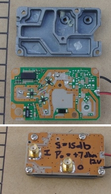
| 11 May 2010 | I thought I'd try converting an old Ku band LNB into a 10GHz amplifier. All the components for the mixer and IF amplifiers were removed from the board. This leaves a two stage FET amplifier. SMA connectors were fitted for the input and output connections and coupled to the circuit with 1pF chip capacitors. The measured gain of the device is 15db (less than expected) and the output before compression is +7dbm. With enough drive, the output limits at +12dbm.
|
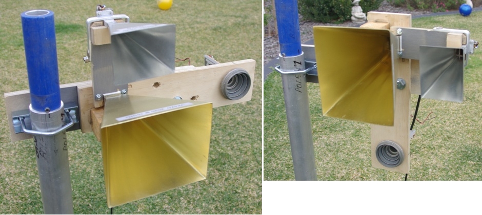
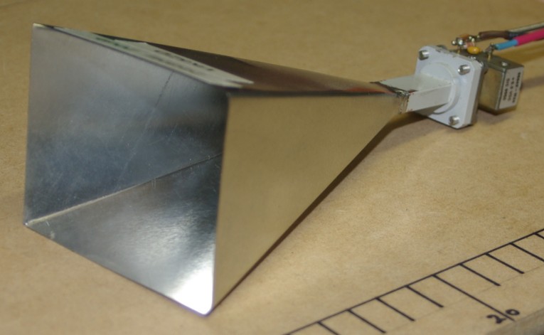
| 09 May 2010 | I constructed another horn antenna for 10GHz. This one has a calculated gain of 20db and will be used as part of a compact microwave antenna system for use on field days. It has been mounted with the 24GHz horn such that it can be set for either vertical or horizontal polarisation.
|
| 01 May 2010 | I tested the 70cm and 2.4GHz yagis in the field today and both worked well. The 70cm yagi was designed for 432MHz but the best match turned out to be on 435MHz. Not quite to plan, but it still works OK at 432MHz (i.e. the transmitter, an FT-897, didn't object). Good front to back. A couple of small lobes to the SE and SW (with the antenna point north) but certainly good enough for a portable field day antenna.
|
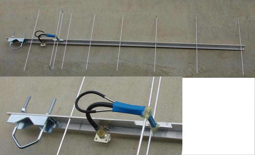
| 30 Apr 2010 | I built another field day yagi using the T-Boom contruction technique. This one is an 8 element for 70cm with an overall length of 131cm. Again, I modified the design slightly to allow for rear mounting to the mast. I refrain from cutting out the entire vertical section of the boom at the driven element so that it retains it's rigidity. The driven element also goes through the boom. The vertical blue 'thing' on the driven element is just a plastic wall plug glued on to provide some support. There is also a 1/4 wave section of 75 ohm line between the driven element and the N connector to improve the match.
|
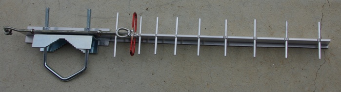
| 29 Apr 2010 | Today I built a 10 element (i.e. small) yagi antenna for 2.4GHz field day use. The overall length is about 42cm. I used a modification of the T-Boom Yagi contruction technique described in the December 2009 issue of Amateur Radio magazine. I trimmed the width of the boom as I thought it might affect the performance because it was quite a large percentage of a wavelength. I also replaced the N connector with a length of hardline and an SMA socket at the rear.
|
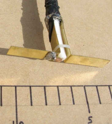
| 20 Apr 2010 | Last Thursday I aquired a 2.4GHz gridpak antenna which I intend to modify for use on 5.7GHz by changing the feed. I 'disassembled' (hammer, saw, etc.) the 2.4GHz to see what it was like. It's basically a dipole and reflector. The attached photo shows the dipole with it's 1/4 wave balun. Note that the solder joint between the coax inner and the brass dipole was broken!! I have yet to decide whether to use a bi-quad antenna or a small horn as the 5.7GHz feed.
|
| 17 Apr 2010 | Conducted another test on 24GHz which was more successful this time. The signals were a bit noisy but otherwise quite readable over a distance of 5.1km. Given that I am only using a 20db gain horn and the other station (Tim, VK5ZT) was only using a 10db gain horn, this is quite good. The path loss over this distance is 134db and the received signal would be about -100db. The next step is to increase the antenna gain to 30db at each end (by using small dishes) which should, in theory, increase the line-of-sight range to ~160km for the same received signal strength.
|
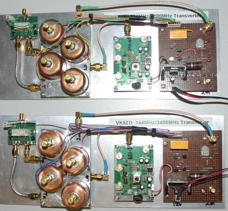
| 15 Apr 2010 | Finally completed transverters #2 and #3 for 3.4GHz. Now I need to do some field testing. Both of these are low power units. The output from transverter #2 is +14dbm and #3 is +17dbm. While EME is certainly out of the question this is more than sufficient for any terrestrial line-of-site contact. The LO on #3 is now only 2.3KHz high, so it's drifting back in the right direction as the crystal ages (it's been running almost continuously for 7 days).
|
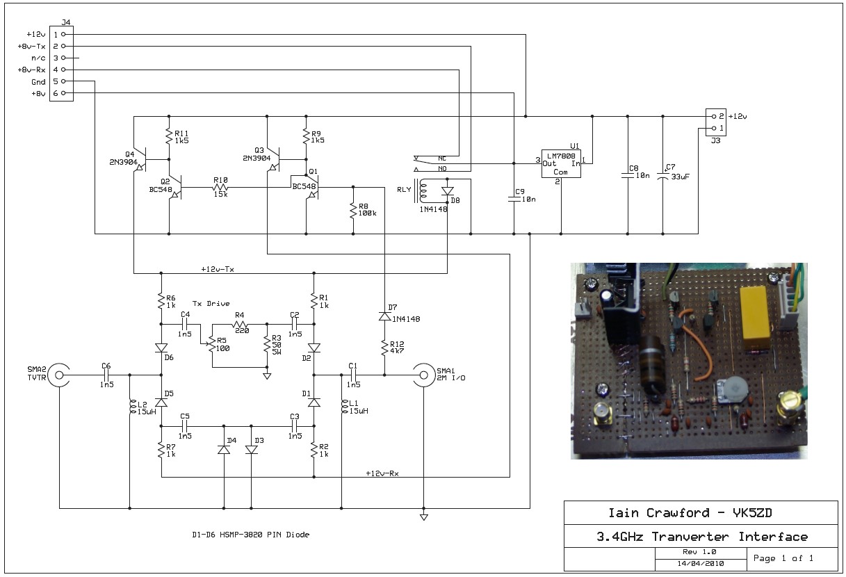
| 13 Apr 2010 | Completed the design and construction of an interface to go between the W1GHZ 3.4GHz transverter board and the FT-290R. Tested transverter #2 on air and all appears to be OK. Producing 25mW output. Now it just needs the antenna changeover relay.
|
| 09 Apr 2010 | Web site updated to display this blog.
|
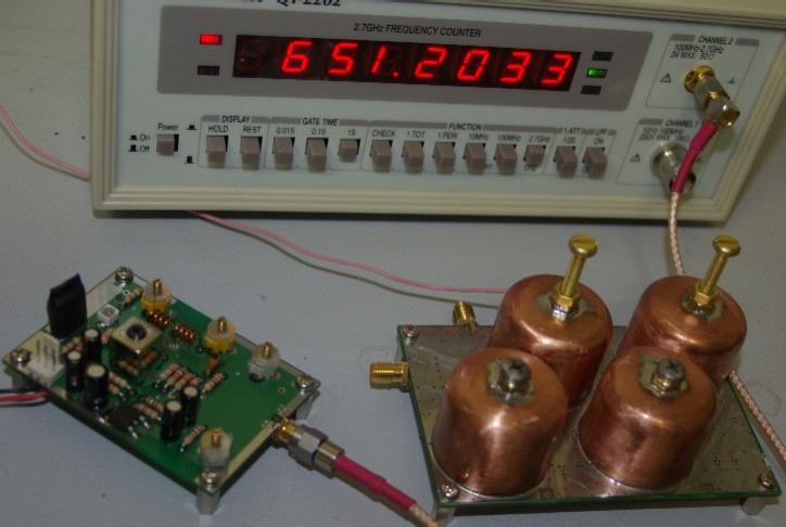
| 08 Apr 2010 | Received EME175 LO kit in the mail. This is for my 3rd 3.4GHz transverter (trying variations of a W1GHZ design). Uses a 108.5333Mhz crystal for an output of 651.2MHz. Kit built and powered up. Output about 1.8KHz high. After 1 hour the output was 3.3KHz high. Seems to be ageing in the wrong direction!
|
| 07 Apr 2010 | Second test on 24GHz using Gunn modules. Tx power ~+7dbm. Antenna ~20db horn. Signals heard over 3km range. Not as good as expected. Later discovered that the battery was going flat :-(
|